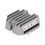
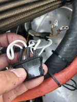
I did a search on VAF and found this photo for wiring the AM101406 on a RV-12 by f1rocket. His description of the wiring as follows: The JD regulator has one less post on it than the Ducati regulator. There's no "R" terminal on the John Deere. That means one of the heavy white wires is not used and can be tied off to the wiring bundle. They come from the same source anyway so it doesn't hurt anything. Be sure to cover the end with some shrink tubing to insulate it from shorting out against the firewall. The remaining heavy white wire is connected to the "B" terminal. Also, on both regulators, terminal "L" is not used. I think it is used to drive an indicator light circuit. The two heavy yellow terminals come from the generator and are connected to the two "G" terminals. Doesn't matter which wire to which terminal. The remaining small yellow wire connects to the "C" or sometimes labeled "F" post. This is the bus voltage detect wire from the ignition switch.

Is this correct wiring for the John Deere AM101406?

-

29mqhrn.png
 
Yes, everything is correct. Although the "C" terminal is probably labeled IGW on the John Deere. The two white wires have previously been spliced together a few inches from the end. So using only one of them does not hurt anything like f1rocket said. Be sure to mount the regulator with heat conductive paste on the aluminum perimeter. The same paste can be used on spark plug threads as recommended by Rotax. The output voltage will probably be a half volt higher than the Ducati, which is good for frequent starts like when giving Young Eagle rides. Van's sells an optional regulator cooling shroud (F-00002) that will NOT fit the John Deere, and duct (DUCT NT 5/8), need 2 feet to go to the cylinder shroud or 1 foot to install like I did to the radiator duct.
IMG_1314a.JPG
 
So I drove to nearest John Deere dealer to get AM101406 voltage regulator and when I opened the box the VR had extension wires instead of spade lug terminal strip at base of unit. No good - plus the cost was $120 :eek::eek:. I guess free economy at work. I ordered a unit on eBay for $27.99 including shipping so we'll see if it matches picture when it arrives next week. I'll probably order a spare for such a bargain price.
 
One more item I forgot to mention... Yesterday when I was troubleshooting to determine if root problem was voltage regulator or battery the D-180 was showing -6 amps current draw. Only equipment running was Facet electric fuel pump, D-180 EFIS, SL40 Comm (idle), GTX 327 Transponder, and Flightcom 403 Intercom (idle). So this is good point of reference...
 
Dbelectrical.com

I got my John Deere alternator from them for $30.60 and free shipping.
Exactly like the pictures posted above.
Plus, the connector for the Ducati reg already has spades on the wires. All I did was insert a very small screwdriver above each spade to bend down the retaining ear and the spade slid right out. Just had to put some heat shrink over them for ground isolation.
It has been working fine in my RV12 for quite a while now.

Which is exactly what I did on my install. 100 hours later and still working great.
 
Today I installed the JD AM101406 Voltage Regulator. Installation was very easy and straight forward thanks to all the help here on VAF. I added an aluminum sub-plate and used Silver Heat Sink Paste to improve cooling.

Question... My battery voltage maintains at 13.8 but amp reading varies a lot from -3 to about +7 in cruise flight. Most of the time amps is just bouncing ~ +/-2 around zero. Is this normal?
 
Yes, the bouncing ammeter is normal for the D-180 RV-12. I do not know if the problem is the shunt on the control board or the D-180. I never tried to fix it. As long as the voltage is above 13.5, I know that the charging system is working. The data download from today's flight show amps varying from neg -145 to pos +291.
 
I recently installed the John Deere regulator exactly like the picture in post 52. The rudder tubes underneath made it difficult to install the new nutplate. If I had it to do over, I would move the regulator left 6 or 7 inches. The voltage is 0.4 higher now.
 
Today I installed the JD AM101406 Voltage Regulator. Installation was very easy and straight forward thanks to all the help here on VAF. I added an aluminum sub-plate and used Silver Heat Sink Paste to improve cooling.

Question... My battery voltage maintains at 13.8 but amp reading varies a lot from -3 to about +7 in cruise flight. Most of the time amps is just bouncing ~ +/-2 around zero. Is this normal?

My ammeter reading has always bounced around like that, with both my Ducati regulators. Never bothered to figure out why, since voltage is good and battery stays charged.
 
Yet Another Ducati VR Fails

Ducati regulator installed under RV-12's panel failed at 120 hrs. Mode was full output for one or two minutes followed by a minute or two of no charge. After several episodes, no recovery.

See picture at post #13, which is the same experience on mine except only one G lead involved. Peeling back the top layer of potting compound revealed massive amounts of solder, but no visible thermal distress.

I cleaned the socket and plug and reinstalled. No output. $23 John Deere VR on order.

Interestingly my SeaRey with Rotax 912ULS has a Ducati regulator that has worked well for more than 350 hours.
 
I had a request for information on how to install the John Deere Voltage Regulator in place of Ducati. So, I searched for my posts in VAF and photos are no longer saved on the hosting site (I wish this could be fixed ? we are losing valuable documentation). Next, I searched my photos and it looks like the ?cloud? sold them to the highest bidder and now they?re gone too.

Can someone pony-up the correct wiring for the John Deere AM101406 Voltage Regulator for the legacy RV-12?
 
The problem is that there are several variations of John Deere voltage regulators.
Purchase one that has the terminals marked like eBay item number:362224250586
-
And another eBay item number:352900565370 has the following
Wire color and function:
(2) Blue Wires: Stator AC in
Red Wire: Battery +
Black Wire: Battery -
Yellow: Ignition switch +
Green: Low charge indicator light
-
Search eBay for "101406 Regulator" which sells for a little as $18.
Can I get a wiring picture of the JD Voltage regulator? Thanks!
 
The terminals on this regulator are labeled. Available on eBay for $20 or less with free shipping.
L = Lamp, IGW = Ignition Switch. 12VDC on IGW enables the regulator.
Be sure to use heat conductive paste between metal parts of the regulator and the aircraft mounting surface.
I also highly recommend forced air cooling.
J_D_Reg.png
 
Last edited:
I mounted the John Deere VR on a thick aluminum sub-plate using heat conductive paste. VR is mounted in original location on firewall shelf. Runs a little warm as indicated by temp strip. No additional forced air cooling. Original Ducati VR quit @ 100TT. JD VR has 800TT and still working fine...
 

Attachments

  • John Deere.jpeg
    John Deere.jpeg
    240.9 KB · Views: 41
The terminals on this regulator are labeled. Available on eBay for $20 or less with free shipping.
L = Lamp, IGW = Ignition Switch. 12VDC on IGW enables the regulator.
Be sure to use heat conductive paste between metal parts of the regulator and the aircraft mounting surface.
I also highly recommend forced air cooling.
View attachment 64546

Thank you sir. My new to me rv12 had a B&C speciality voltage controller. I found both yellow leads burnt up a couple days ago, after my battery slowly losing charge and showing negative amps during an entire flight.
 
I mounted the John Deere VR on a thick aluminum sub-plate using heat conductive paste. VR is mounted in original location on firewall shelf. Runs a little warm as indicated by temp strip. No additional forced air cooling. Original Ducati VR quit @ 100TT. JD VR has 800TT and still working fine...

I have one ordered at my local dealer. My plane had a B&C speciality voltage controller. Mine already has the forced air from the front cowling but I do like the look of that sub plate. Just to make sure I’m correct on what I seen from other posts, can you show me the correct wire hook up? Thanks!
 
I have one ordered at my local dealer. My plane had a B&C speciality voltage controller. Mine already has the forced air from the front cowling but I do like the look of that sub plate. Just to make sure I’m correct on what I seen from other posts, can you show me the correct wire hook up? Thanks!
Talk to B&C. They're good folks and I'm guessing they'd like to see your failed unit. Might even replace or give you some consideration for a new unit.
Also they can tell you if the one you have is the one they designed specifically for our combination of RV12, Rotax, and Battery (can't remember the #) application.
Worth a try,
Dave

Thanks Dave, I’ll send them an email!
 
I have one ordered at my local dealer. My plane had a B&C speciality voltage controller. Mine already has the forced air from the front cowling but I do like the look of that sub plate. Just to make sure I’m correct on what I seen from other posts, can you show me the correct wire hook up? Thanks!
Jesse, Burned wire ends are likely caused by bad connections which make heat. Make sure connections on the new regulator are tight. Each wire terminal should be connected individually so that you can tell how tight it is. If all of the terminals are grouped together in one plastic housing, then the installer can not tell how tight each individual terminal is.
Post the wire size and color of each wire and where it connects to the B&C regulator and I will figure out where to connect them to the John Deere regulator.

It had the plastic housing plug. And the copper wire is 14 gauge. Both of the 14 yellow wires were burnt up. The smaller yellow wire was not.
 

Attachments

  • IMG_1305.jpeg
    IMG_1305.jpeg
    1.8 MB · Views: 37
  • IMG_1306.jpeg
    IMG_1306.jpeg
    1.5 MB · Views: 36
  • IMG_1308.jpeg
    IMG_1308.jpeg
    1.6 MB · Views: 37
Last edited:
It had the plastic housing plug. And the copper wire is 14 gauge. Both of the 14 yellow wires were burnt up. The smaller yellow wire was not.
The two large yellow wires come from the generator and are AC input to the regulator. The small yellow wire connects to the John Deere IGW terminal and enables the regulator. The white wire(s) connect to B+. At least that is the way my plane is wired. Vans made changes over the years.
 
The two large yellow wires come from the generator and are AC input to the regulator. The small yellow wire connects to the John Deere IGW terminal and enables the regulator. The white wire(s) connect to B+. At least that is the way my plane is wired. Vans made changes over the years.
Thank you sir! Gonna try to get everything installed and buttoned up tomorrow afternoon.
 
Did you try your B+C after you repaired the burnt wires with new individual spades. A few weeks ago my one year old $350 B+C quit and had burned one of the yellow generator wires. Had about 75 hrs. on it. I cut the wire back and put a new spade on it and installed them all back on tightly with some dielectric grease ,like I thought I had a year ago when I replace the Ducati that had lasted for 3 yrs and 300 hrs. After running the manuals test for generator and all looking good I tried the B+C and it worked fine. It has about 5 hrs on it and Okay. Probably just jinxed myself! The JD.one that I tried after the Ducati was putting out about 14.7-14.9 volts with fully charged battery. Worried me that it was to high. It seems from what I’ve read that some people get one that work great and some don’t. I do carry one in my airplane kit .
 
The D-180 data log can be downloaded to a computer and analyzed with Excel.
Was the voltage high when the charging current was high?
Put a charger on the battery and charge it up. Take the charger off. Wait until the next day, then measure the battery voltage. It should be 12.5 to 13 volts. A load test on the battery is also a good idea.
Low voltage and zero charging current indicates a bad voltage regulator, regardless of the battery condition.
John Deere part numbers: AM101406, or MIA881279, or JDR1406
The John Deere regulator terminals are different than the Ducati. So not plug and play.
Screenshot_20240614_211325_Gallery.jpg

I have a ULS that had the Ducati fail at 120 hours. I bought (4) AM101406'S and pre-wired as shown in pic. The wire colors mentioned are as they were attached to the Ducati. When I op's checked them, 1 put out 13.2v so tossed it. Another put out 14.9v so I tossed that one too. The 3rd put out 14v and the 4th 13.8. I installed the 14v and keep the 13.8 on board for a spare. I relocated VR to below passenger side instrument panel and use passenger vent to direct (via a tube) blast air on it. 230 hours now with no issues on a $25 VR.

Mich48041,
I did not intend to attach my post to yours. My apologies.
 
Last edited: