

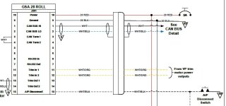
OK, I've done a lot of reading (including AeroElectric) and looked at plenty of other designs and I think I'm ready for initial feedback on my tentative electrical system design for my future RV-10. Some notes:

Notes on my design drawing:

- Primary mission: cross-country IFR
- Redundancy: high redundancy for both flight safety AND convenience (e.g. not as likely to get stuck somewhere)
- Design: two separate busses with ability to cross-connect (z14 design)
- Bus #1: "clearance bus" designed to operate on ground prior to starting engine
- Bus #2: "main bus" in-flight convenience features
- Fault tolerance: flight can continue with little or no side effects with failure of either bus (battery, alternator, and/or contactor)
- Ultimate failsafe: dual pMags plus G5 (w/ battery) plus Foreflight plus handheld backup radio
- Without alternator(s): Bus 1 battery should last 49-91min; Bus 2 battery should last 21-66min (without any load shedding)
Notes on my design drawing:
- Not comprehensive -- doesn't include many details such as most wire sizes, sensors, minor items, etc.
- Somewhat figurative -- some connections won't be wired exactly as shown
- Contactors -- these contactors appear to be very robust and don't need external diodes
- Bus 1 and Bus 2 switches -- may rename, but each DPST switch controls its bus by turning both the battery and alternator on/off
- Circuit breakers -- only for items I want to be able to disable during flight
- Runaway trim -- need to pull both the AP and Trim breakers to fully disable trim
- Crossfeed -- still researching the maximum voltage differential between the two batteries where it would be safe to engage with both batteries "on", but generally it shouldn't be necessary to engage the crossfeed with both busses enabled. On the other hand, the batteries will be next to each other with very short runs of large wire, so it may be able to handle quite a bit of voltage differential.
- Am I missing any major electrical items?
- Any logical or procedural errors?
- Any incorrect fuse/breaker/wire sizes (for the wires where size is shown)
- Any safety/failure things I am overlooking?
Last edited:
")

