What's new
Van's Air Force

Don't miss anything! Register now for full access to the definitive RV support community.

Alternator field voltage?

Richard RG

Active Member
Recently while happily flying along, noted during one of my panel scans that I had a new project. The voltmeter indicated 12.4v rather than the expected 14.2v it had always indicated. After doing the basic checks confirming I still had an alternator belt and that the belt tension driving the pulley on the Electrosystems 60 amp (PN:ALX8421RS) alternator was correct, then started checking connections/breakers and wiring for continuity, finding no faults.
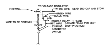
Being mostly electrically challenged, then downloaded trouble shooting flow sheets from the internet. With the master switch on, then probed for voltages. The battery had been charged up to 12.6v and was able to confirm 12.6v into the Lamar 14v external voltage regulator (PN: B-00267-2) Also installed is a Lamar overvoltage relay module PN B-00339-1 and having 12.6v indicated here as well.
Probing the yellow field wire out of the regulator to the alternator field terminal indicated 6.4v. The alternator field terminal connection indicated 6.4v as well.
My question is, should the field terminal voltage have been within one volt or so of buss voltage? Having zero luck finding specs on the expected field voltage from this regulator powered up and engine off, surmised that 6.4v may be the the correct field voltage to allow the alternator to carry a light load during start up and then ramp up (increase field voltage) alternator load if required, after start up.
Not knowing how to proceed, then decided to confirm if the alternator may be the problem. As per my newly acquired internet education 'full fielded' the alternator. After removing the field wire from the regulator to alternator, installed a jumper wire from the power output terminal of the alternator to the alternator field terminal post. Ensuring that all expensive electrical things wouldn't be exposed to the hoped for high voltage spike started up the engine and instantly pegged the volt meter at 16+ volts.
After confirming that the alternator appeared good. went back to head scratching and probing for voltages again... only to discover that the field voltage out of the regulator is now a solid zero with t 12.6v to the regulator.
It appears at this point that I may need a new regulator as I may have cooked it, due to my full fielding test? I am hoping that the 6.4v field output from the regulator was the source of my no charging issue and no big deal that I may have fried an already semi fried regulator.
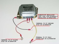
I'm hoping someone can confirm (or not) that the regulator was the problem and if so recommend a similar three wire replacement regulator. The current regulator has red power supply wire, black ground wire to airframe and yellow field wire to alternator. Thanks for reading, cheers
 
I can tell you my plane the field voltage is about 1 volt less than battery voltage WITH THE ENGINE NOT RUNNING. I have a three position toggle outputting to my IE voltammeter, UP is field voltage and DOWN is bus voltage. Laugh if you will LOL nobody else in the world has a field volts monitor in their plane, but I wanted to know what the field volts were while the alternator was working and connected the toggle switch that way.

Regarding full fielding, when I did that to check my alternator, I took the VR out of the circuit completely, I bypassed it and took the 12 volt signal input to the VR and ran it strait to the field terminal on the alternator…. thats full fielding.. you kinda sorta did it a different way by applying battery power to the alt field from the bus but left the input to the VR connected, that may have fried the VR. But either way if you had less than bus volts at your input to your VR you have a problem.

What you need to do is put a good 12 volt signal on the input to the VR and see what you have as an output, you should have bus voltage or within 1 volt of bus, thats what I have. Once the engine is running the field voltage will go down to 5 volts or so, varying with load, but to kick on it needs 12 volts, thats starts the alternator, than once the VR sees 14 volts it decreases the field to maintain 14
 
Last edited:
I can tell you my plane the field voltage is about 1 volt less than battery voltage WITH THE ENGINE NOT RUNNING. I have a three position toggle outputting to my IE voltammeter, UP is field voltage and DOWN is bus voltage. Laugh if you will LOL nobody else in the world has a field volts monitor in their plane, but I wanted to know what the field volts were while the alternator was working and connected the toggle switch that way.

Regarding full fielding, when I did that to check my alternator, I took the VR out of the circuit completely, I bypassed it and took the 12 volt signal input to the VR and ran it strait to the field terminal on the alternator…. thats full fielding.. you kinda sorta did it a different way by applying battery power to the alt field from the bus but left the input to the VR connected, that may have fried the VR. But either way if you had less than bus volts at your input to your VR you have a problem.

What you need to do is put a good 12 volt signal on the input to the VR and see what you have as an output, you should have bus voltage or within 1 volt of bus, thats what I have. Once the engine is running the field voltage will go down to 5 volts or so, varying with load, but to kick on it needs 12 volts, thats starts the alternator, than once the VR sees 14 volts it decreases the field to maintain 14
Thanks for the reply Ruready and not laughing that you can monitor your field voltage, I think it a brilliant idea. I had buss voltage (12.6v) to the VR with the engine not running and had 6.4v from the VR to the alternator field terminal, again with the engine off.
Based on your reply that you see about a 1 volt drop across your regulator would lead me to believe my VR had failed, as field voltage out of the VR was roughly 6 volts less than the battery input voltage to the VR.
Due to my full fielding of the alternator, without fully isolating VR may have fully fried the VR, so really hoping I had fully fried an already defective VR.
In any case, at this point it looks like I will be shopping for one of those pricey aircraft voltage regulators and hoping someone else can confirm that a 1 volt drop across the VR is the expected voltage drop across a good voltage regulator.
 
I wouldnt rush out to by a new VR, those input signal can be wierd, it may look good but once you put a load on it it can not handle anything.. make sure that 12 volt input IS A GOOD SIGNAL, try to power something with it, like the full field to the alternator
 
Last edited:
I wouldnt rush out to by a new VR, those input signal can be wierd, it may look good but once you put a load on it it can not handle anything.. make sure that 12 volt input IS A GOOD SIGNAL, try to power something with it, like the full field to the alternator
Too late... I've already rushed out and ordered a used identical VR off ebay for $225.00c. with shipping in the price. Hope the used one works. First check after the replacement VR is installed will be looking for a 1 volt difference between buss/battery input voltage to the VR and field voltage out. Really hoping the VR is the problem and expect that if I see the 1 volt drop across the VR should have an alternator that might put out current again, Because the flying season is fairly short in my part of the world, want to get airworthy sooner rather than later.
 
The 'full fielded' alternator test likely resulted in a voltage much higher than the voltmeter is capable of displaying.
That high voltage could have destroyed the regulator. Double check voltage measurements to be sure that the over-voltage relay is not open.
When testing unloaded circuits, digital voltmeters with high internal impedance can display normal voltages even in defective circuits. The meter is not wrong. It just requires an understanding of ohm's law. When testing circuits with a digital meter, a load should be connected. A small test light makes a good load.
In many cases, I like to use a test light instead of a voltmeter for trouble shooting because it provides both a load and an indication of 12 volts. Harbor Freight sells a test light for $3.99. Search their website for part number 63603.
Need to be carefull with these kind of tests here, as you can damage the alternator. FYI, VRs do not modulate alt output by changing field voltage, they do so by changing field current. Voltage may or may not change as the VR changes the current, but those changes are not definitively related to what the VR is trying to do.

Larry
 
Thanks to Mich48041 for finding this Beechcraft Service Instruction SI 1062 showing what the B00339-1 overvoltage relay is and how it is connected in series between the alternator field switch and the voltage regulator. AFAIK this overvoltage field interrupter relay comes from a former time, before overvoltage crowbars. Relevant image snipped from the Beechcraft SI attached.

AFAIK you can replace the regulator with a "Ford" VR166. For instance Standard Motor Products is good quality IMO.

Bob Nuckolls troubleshoots an external voltage regulator by doing a temporary swap of a "Ford" VR166. Image attached.

It would be a good idea to verify the function of the overvoltage relay, the Beechcraft SI 1062 says it should trip at 16 +/- 0.2 V. I personally would use an adjustable power supply versus the engine-running method in the SI.
 

Attachments

  • Lamar B00339-1 overvoltage relay snip from Beechcraft SI 1062.png
    Lamar B00339-1 overvoltage relay snip from Beechcraft SI 1062.png
    39.9 KB · Views: 23
  • externa regulator test by temporary swap with Ford VR166.jpg
    externa regulator test by temporary swap with Ford VR166.jpg
    81.5 KB · Views: 25
Last edited:
Just FYI, I am probably the only person to ever connect a DT toggle to a voltmeter in my plane… but after having a couple charging system issues and getting quite familiar with alternators and electrical systems over the past 4 years, I was curios what the field voltage was while the alternator was working. While flying yesterday I flipped the Electrinics International VA-1A volt/ammeter toggle from bus volts to off and than to field volts and the meter would constantly jump from 3 volts to 10 volts.. maybe a little higher cant remember for sure, but did see it jump like crazy never staying the same for more than a blink of an eye.. just 3.. 6… 10… 3.. 5.. 10.. with the backlight flickering on and off the whole time, I just looked over at the IE webste https://iflyei.com/product/va-1a-volts-amps-instrument/ and found the required volts are 7.5 or working volts are 7.5 to 40 volts, so that explains the backlight flickering on and off. So someone mentioned the VR regulates the buss voltage by current and not voltage like I thought, so now I am curious what the VA-1A would have showed if I flipped its little toggle over to AMPS…. another reason to go flying today…
 
Last edited:

Attachments

  • Z00.pdf
    18.5 KB · Views: 9
Last edited:
Back
Top