

I have had quite a few requests from other builders for the electrical layout of our RV-3 project. While the electrical system has been up and running for months now, it has taken awhile for me to get back to the computer to make updates to my fabrication drawings to reflect the “as built” configuration, and I didn’t want to put it out there until I had been able to show the “final” version (like anything is ever final in an experimental design….). Last night I had a chance to do a few revisions, so here is what I call the “Systems Level” drawing of the electrical bus structure. NOTE THAT IT IS NOT A WIRING DIAGRAM!! It does not show all of the circuit protection, wire sizes, or fabrication notes needed to actually assembly it – this is simplified to show how it works. I also want to point out that I am not an Electrical Engineer – but I sure do work with a lot of them! I describe my design goals below, and readily acknowledge that there are numerous ways to achieve them. Is this the “BEST” way? There’s no way I’d claim that, but it is the product of a lot of discussions and iterations with some smart folks. (A tip of the hat - Much of my philosophy comes from studies of the classics – Bob Knuckolls, Tony Bingelis, and the many GA airplanes I have worked on over the years.)
So a few notes might help illuminate the design. My overall design philosophy was to build a system that was reliable, redundant, fault tolerant, and easy to operate. Reliability is (partly) inversely proportional to the number of parts that you have – keeping the parts count low, and using quality parts helps. I like redundancy, so that if the real-world quality doesn’t meet the expected standards, you still have the functionality that you need. Fault tolerance comes from looking at the types of faults you might expect (loss of power source, open circuits, and short circuits), and building in alternate ways of assuring that you can get power to the important boxes even if those faults occur. And simplicity 0f operation? My goal is that once the pilot turns it on, he or she shouldn’t have to touch it again until it is time to turn it off - or the actions that need to be taken are so simple and intuitive that it is virtually “set and forget”.
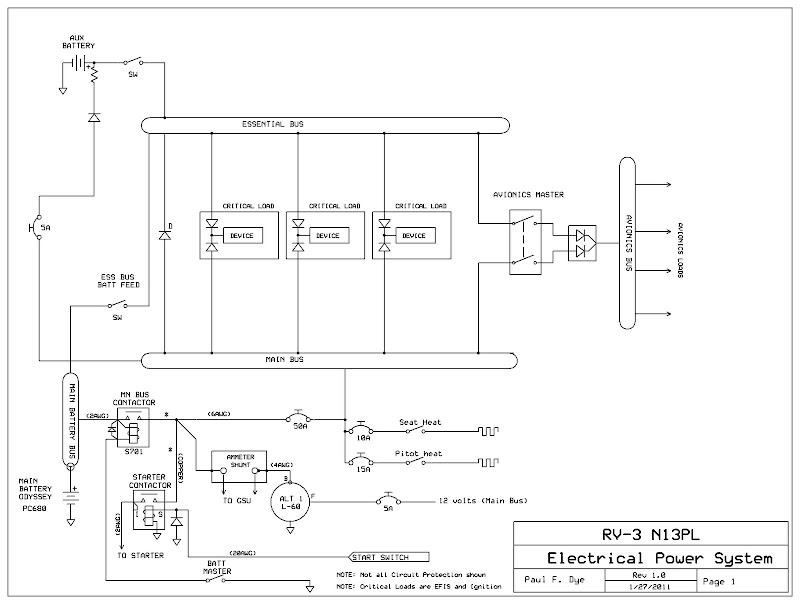
So how does this system work? Basically, it relies on all critical loads being fed from multiple sources (through diodes), and then having multiple paths (busses) to supply the power, and multiple power sources (main battery, Aux battery, Alternator) to supply power to those busses. Let’s look at buses – if any bus shorts to ground, it can be switched off, and power can still be supplied to the important loads from another bus. For critical loads (EFIS, electronic ignition, etc), there is no difference between busses. Non-critical loads are supplied from the main bus only – by definition, you can live without them (lighting, heaters, 12 volt power outlets, etc.). Each bus can be powered from multiple sources – the Main from either the battery or alternator, the Essential from the Main, the Battery, or the Aux battery, and the Avionics bus from the Main or Essential. (Turn the Avionics Master on, and it gets power from whichever is the better supply.)
Note that I make a distinction, with an all-glass cockpit airplane, between the EFIS and the Avionics. The EFIS consist of instrumentation that I simply don’t want to leave the ground without – not only the attitude platform and sir data computer, but engine instruments as well. I consider the Avionics to be the transponder, Comm system – and yes, the IFR GPS box. I consider these “peripheral” to survival so long as the EFIS has its own internal GPS that can be used as a backup (the G3X system has two of them). In this airplane, I can turn off the Avionics bus (if it has a short), and still find my way easily to a runway.
The Aux battery has more than enough power to keep the EFIS running until I can find a runway (assuming that I have killed both the alternator and the Main battery, which would power the EFIS long after I have run out of fuel). The other big benefit of the Aux battery is that it protects the EFIS from the big voltage sag during engine start – which allows booting up the system as soon as you get in the cockpit, expediting departure and minimizing ground run time on the engine.
The beauty of diodes is in my final requirement – “set it and forget it”. Turn on the Master and the Aux Battery before engine start, and unless you smell smoke or get a low voltage warning, leave everything on until you have finished the flight. If you have a low voltage, power off the big loads (lights, Avionics if it looks like the battery isn’t going to be up to the task…) and find a place to land. Although it might sound complex to say it is a “three-bus, three source, redundant system”, the truth is, it just isn’t very complicated. The normal master/starter contactors and their associated switches are the most complicated (looking) things on the drawing, and they are standard.
So now you know – one way to build a fairly robust system without a lot of moving parts.
Paul
So a few notes might help illuminate the design. My overall design philosophy was to build a system that was reliable, redundant, fault tolerant, and easy to operate. Reliability is (partly) inversely proportional to the number of parts that you have – keeping the parts count low, and using quality parts helps. I like redundancy, so that if the real-world quality doesn’t meet the expected standards, you still have the functionality that you need. Fault tolerance comes from looking at the types of faults you might expect (loss of power source, open circuits, and short circuits), and building in alternate ways of assuring that you can get power to the important boxes even if those faults occur. And simplicity 0f operation? My goal is that once the pilot turns it on, he or she shouldn’t have to touch it again until it is time to turn it off - or the actions that need to be taken are so simple and intuitive that it is virtually “set and forget”.
So how does this system work? Basically, it relies on all critical loads being fed from multiple sources (through diodes), and then having multiple paths (busses) to supply the power, and multiple power sources (main battery, Aux battery, Alternator) to supply power to those busses. Let’s look at buses – if any bus shorts to ground, it can be switched off, and power can still be supplied to the important loads from another bus. For critical loads (EFIS, electronic ignition, etc), there is no difference between busses. Non-critical loads are supplied from the main bus only – by definition, you can live without them (lighting, heaters, 12 volt power outlets, etc.). Each bus can be powered from multiple sources – the Main from either the battery or alternator, the Essential from the Main, the Battery, or the Aux battery, and the Avionics bus from the Main or Essential. (Turn the Avionics Master on, and it gets power from whichever is the better supply.)
Note that I make a distinction, with an all-glass cockpit airplane, between the EFIS and the Avionics. The EFIS consist of instrumentation that I simply don’t want to leave the ground without – not only the attitude platform and sir data computer, but engine instruments as well. I consider the Avionics to be the transponder, Comm system – and yes, the IFR GPS box. I consider these “peripheral” to survival so long as the EFIS has its own internal GPS that can be used as a backup (the G3X system has two of them). In this airplane, I can turn off the Avionics bus (if it has a short), and still find my way easily to a runway.
The Aux battery has more than enough power to keep the EFIS running until I can find a runway (assuming that I have killed both the alternator and the Main battery, which would power the EFIS long after I have run out of fuel). The other big benefit of the Aux battery is that it protects the EFIS from the big voltage sag during engine start – which allows booting up the system as soon as you get in the cockpit, expediting departure and minimizing ground run time on the engine.
The beauty of diodes is in my final requirement – “set it and forget it”. Turn on the Master and the Aux Battery before engine start, and unless you smell smoke or get a low voltage warning, leave everything on until you have finished the flight. If you have a low voltage, power off the big loads (lights, Avionics if it looks like the battery isn’t going to be up to the task…) and find a place to land. Although it might sound complex to say it is a “three-bus, three source, redundant system”, the truth is, it just isn’t very complicated. The normal master/starter contactors and their associated switches are the most complicated (looking) things on the drawing, and they are standard.
So now you know – one way to build a fairly robust system without a lot of moving parts.
Paul
Last edited:


