Rjmvmi1998
Member
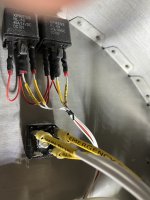
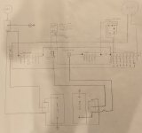
I have an interesting problem here, looking for some advice on where to trouble shoot. RV10 with two earth X batteries. Electrical systems designed for two batteries, 1 main and 1 standby (which is continuously tied to the main under normal conditions when system voltage is above 12V and then automatically disconnects when voltage drops below 12V). The batteries power 1 main buss which in-turn powers 1 endurance buss. The main and endurance buss is connected with a diode (a four prong transformer rectifier) to allow main buss voltage to power the endurance buss but prevents the endurance buss from powering the main buss. Endurance buss is connected directly to standby battery via a direct feeder circuit to the standby battery and switched on/off in cockpit
So I hope I explained that well enough to understand the basic architecture.
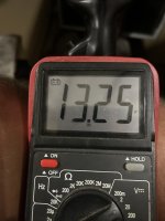
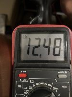
So here is my problem, I’m experiencing voltage drop on the endurance buss during normal operation. I removed the standby battery to start my trouble shooting, so all voltage into the system is coming from one battery and it is is fully charged reading 13.28 volts under a small load, probably 3 amps. With the battery switch on, the main buss voltage is reading 13.25 volts, and the endurance buss is reading 12.48 volts. With the battery switch off and the endurance switch on, the endurance buss is reading 13.25.
So I’m getting a voltage drop of .75 volts between my two busses under normal operating conditions. The obvious suspect is something in the diode pack connecting the two busses is causing this but wanted to put it out there to see if anyone else has a suggestion.
Thanks
Robert
.
So I hope I explained that well enough to understand the basic architecture.
So here is my problem, I’m experiencing voltage drop on the endurance buss during normal operation. I removed the standby battery to start my trouble shooting, so all voltage into the system is coming from one battery and it is is fully charged reading 13.28 volts under a small load, probably 3 amps. With the battery switch on, the main buss voltage is reading 13.25 volts, and the endurance buss is reading 12.48 volts. With the battery switch off and the endurance switch on, the endurance buss is reading 13.25.
So I’m getting a voltage drop of .75 volts between my two busses under normal operating conditions. The obvious suspect is something in the diode pack connecting the two busses is causing this but wanted to put it out there to see if anyone else has a suggestion.
Thanks
Robert
.