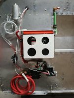
Finishing up on firewall electric. Trying the setup out. Master switch to ground works fine closing relay giving 12V. Then ran the 12v to starter relay. It worked as it should, had 12V coming out. However, It was drawing 3.3 Amps. Question: Is this normal or do I have something

Van's Air Force
You are using an out of date browser. It may not display this or other websites correctly.
You should upgrade or use an alternative browser.
You should upgrade or use an alternative browser.
Starter relay amp draw
- Thread starter FuturPilot
- Start date

About normal for a starter relay. The master relays draw around amp.
Thanks, might be on the right track. Forge ahead. Build on.
That is why the starter relays are rated for momentary only, whereas the master are continuous dutyThe coil in the CH24021 is 3.8 ohms. I=V/R would suggest the you'd measure 3.3A at 12.8V.
The coil in the CH24115 (Master Contactor) measures 17.5 ohms. It should draw .73A at 12.8V.
That is why the starter relays are rated for momentary only, whereas the master are continuous duty
Not really. Intermittent vs continuous has more to do with heat rejection and materials of construction of the device. Typically the former has to be sufficient to not affect the latter.
The consequences of a stuck relay can be a bit more dramatic for a starter vs a bus. In general, the related spring tends to be stronger -> more power required -> more amp draw
Correct - in the terms of power, the Master Contactor burns 9.34 watts, the Starter 42.24 watts.Not really. Intermittent vs continuous has more to do with heat rejection and materials of construction of the device. Typically the former has to be sufficient to not affect the latter.
The consequences of a stuck relay can be a bit more dramatic for a starter vs a bus. In general, the related spring tends to be stronger -> more power required -> more amp draw
A builder's widow donated his half built airplane to his EAA chapter. There are 2 contactors. One of them is mounted on the engine side of the firewall and has "MASTER" handwritten on it. It has two large terminals and one small terminal. The part number on it is 70-111225-5. I measured 114 ohms across the coil. I am confident that is the master contactor.
The other contactor is mounted next to where a rear-mounted battery is intended to be installed. This second contactor has two large terminals and two small terminals. I measured 17.2 ohms across its coil. The part number on this contactor is X61-0017. An internet search of this part number did not give its intended purpose, master or starter. I suspect it is intended as an intermittent starter contactor. But Brian Decker's post #5 above states that part number CH24115 (Master Contactor) has 17.5 ohms. Now I am not so sure.
The other contactor is mounted next to where a rear-mounted battery is intended to be installed. This second contactor has two large terminals and two small terminals. I measured 17.2 ohms across its coil. The part number on this contactor is X61-0017. An internet search of this part number did not give its intended purpose, master or starter. I suspect it is intended as an intermittent starter contactor. But Brian Decker's post #5 above states that part number CH24115 (Master Contactor) has 17.5 ohms. Now I am not so sure.
The master contactor will generally have internal wiring for the coil such that grounding the coil will energize the contactor.A builder's widow donated his half built airplane to his EAA chapter. There are 2 contactors. One of them is mounted on the engine side of the firewall and has "MASTER" handwritten on it. It has two large terminals and one small terminal. The part number on it is 70-111225-5. I measured 114 ohms across the coil. I am confident that is the master contactor.
The other contactor is mounted next to where a rear-mounted battery is intended to be installed. This second contactor has two large terminals and two small terminals. I measured 17.2 ohms across its coil. The part number on this contactor is X61-0017. An internet search of this part number did not give its intended purpose, master or starter. I suspect it is intended as an intermittent starter contactor. But Brian Decker's post #5 above states that part number CH24115 (Master Contactor) has 17.5 ohms. Now I am not so sure.
Conversely, the starter contactor will require 12v to the coil to energize it.
Also, the master contactor is close to the battery, in general. The starter contactor is generally close to the starter.
The X61-0017 is a Lamar part used by Cessna and others for the "Master" relay function. It is designed for continuous duty. The big lugs connect to the big wires (2GA), and the little lugs are used for activation -- this unit requires a +12V on one side of the coil, and switched to ground on the other one.
(see https://irp.cdn-website.com/d25e75f5/files/uploaded/ContactorInfo.pdf) -- "Negative Turn On" (....what an old-ex-girlfriend once called me....)
The 70-111225-5 is a White-Rodgers relay also designed for continuous duty. Same as before - Big Lugs - Big Wires, Little lugs go to ground, and +12 to enable it (usually connected to a 3A breaker and switch labeled "START" or Keyswitch "START" position.
Coil should measure 16 Ohms -- 114 Ohms means the part # is incorrect, the measurer didn't connect something right, or the coil is deffective.


Edit: Also, install some suppression diodes across the coil so the switches don't get arc'd-to-death...
Edit: I wouldn't use the 70-111225-5 for the Starter Relay -- the current rating isn't high enough (only 80A continuous, 150A inrush) to support the starter motor.
(see https://irp.cdn-website.com/d25e75f5/files/uploaded/ContactorInfo.pdf) -- "Negative Turn On" (....what an old-ex-girlfriend once called me....)
The 70-111225-5 is a White-Rodgers relay also designed for continuous duty. Same as before - Big Lugs - Big Wires, Little lugs go to ground, and +12 to enable it (usually connected to a 3A breaker and switch labeled "START" or Keyswitch "START" position.
Coil should measure 16 Ohms -- 114 Ohms means the part # is incorrect, the measurer didn't connect something right, or the coil is deffective.
Edit: Also, install some suppression diodes across the coil so the switches don't get arc'd-to-death...
Edit: I wouldn't use the 70-111225-5 for the Starter Relay -- the current rating isn't high enough (only 80A continuous, 150A inrush) to support the starter motor.
Last edited:
Thanks rocketman1988 and bjdecker. Evidently both contactors are continuous duty and neither should be used for the starter. I will double check the coil resistance that measured 114 ohms. I will also apply 12 volts to each coil to see if each contactor pulls in and does not overheat. Looks like it will be necessary to purchase a new starter contactor.
Agreed, it is excessive heating that will fail the coil components when the intermittent relay is used in a continuous application. But the heat comes from the higher current that the coil consumes. That provides a more robust action to the contactor, with heating being the adverse effect.Not really. Intermittent vs continuous has more to do with heat rejection and materials of construction of the device. Typically the former has to be sufficient to not affect the latter.
The consequences of a stuck relay can be a bit more dramatic for a starter vs a bus. In general, the related spring tends to be stronger -> more power required -> more amp draw
