Bavafa

Well Known Member
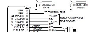
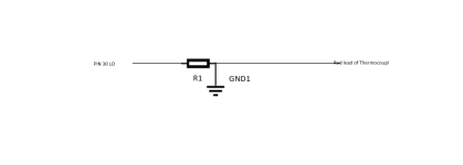
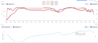
I have installed a K type temp probe in the engine area and is linked to my GE24. I do see temp and at room temperature, it seems accurate but as the temp rises under the cowl, I does not seem to trend correctly.
I also tried to verify the temp setting it next to another thermometer with the heat gun at it but also did not seem to jib consistently.
I was wondering if there is a way I can calibrate this type of prob in the G3X?
 
In my experience a properly functioning thermocouple is typically very accurate. It would be helpful if you could describe what input configuration you are using, type of wiring, type of connectors, which pins on the GEA 24 each wire from the thermocouple is connected to, etc.
 
FWF T/C wire

My 2 K type probes in my FWF were very accurate right out of the box. Agreed maybe a little more detail is needed.
 
I am using pin 30/31 (J243) and using an inexpensive*k type thermocouple (https://www.amazon.com/dp/B07PXWP99N?psc=1&ref=ppx_yo2ov_dt_b_product_details)

G3X has been configured for POS6 as K type.
This is installed right next to my battery under the cowl.* The OAT today was around 85F and it read correctly.* But when I started the engine and taxied, the temp actually*went down, as low as 64F. I know I don't have the wires (HI/LO) reversed as I tested for that. When I put a heat gun on it, the temp climbs right away but it does not jib with another thermometer right next to the sensor.*
I am going to check the accuracy of the other thermometer but if you can recommend a different K type thermocouple, that would be great.
 
Type K Wire Color Code?

Check the wiring polarity, this is sometimes a problem. Note for US Type K the positive lead is Yellow and the negative is Red.


US
(+) - Yellow
(-) - Red
Cable Jacket - Brown (Extension Cable - Yellow)

IEC
(+) - Green
(-) - White
Cable Jacket - Green

UK
(+) - Brown
(-) - Blue
Cable Jacket - Red
 
Thermocouple Troubleshooting

I am having a bit of a hard time finding a datasheet for this particular sensor, so I cannot provide a definitive answer here. If you were provided with one, please email it to [email protected].

If this is an ungrounded thermocouple, a DC reference must be added to the Lo input. See page 23-36 of the G3X Touch Installation manual (Rev. AT) for more information on that aspect of the installation.

Thanks,

Justin
 
Last edited:
Thermocouple type

I used this type before. I went with ungrounded and added the resistors. I went with ungrounded to improve the accuracy but either should be ok.

Universal Cylinder Head Temperature CHT Sensors K Type Thermocouple with 10mm Inner Diameter Washer & 10 feet Cable https://a.co/d/c5cVsVS
 

Attachments

  • Screenshot 2023-07-25 141437.jpg
    Screenshot 2023-07-25 141437.jpg
    15.1 KB · Views: 55
Last edited:
I am having a bit of a hard time finding a datasheet for this particular sensor, so I cannot provide a definitive answer here. If you were provided with one, please email it to [email protected].

If this is an ungrounded thermocouple, a DC reference must be added to the Lo input. See page 23-36 of the G3X Touch Installation manual (Rev. AT) for more information on that aspect of the installation.

Thanks,

Justin

Hi Justin,
I don't have the specifications for this thermocouple but it is the type that the two ends are just connected together. The probe is connected to the airframe which has the ground and since the two ends are also connected, I get continuity to the ground at both leads. Here is more detail about the behavior. All temp reading are from the engine page.

- The probe reads OAT correct when installed first
- If I apply heat to it, the temp rises right away and cold will reduce the temp
- When I put the cowl on and run the engine, the temp actually goes down instead of up
- The behavior is the same if the probe is connected to the airframe or NOT (grounded or NOT).
- The behavior is the same with a 1M Ohm resistor between Lo input and the ground
- I have shut down all other power in the aircraft, including master and alternator to make sure other electronics are not affecting this and the behavior was the same.
- I have tested two different probe of same type and different spade connected and all have been the same

Installed a bluetooth temp sensor under the cowl to check for actual temp, sure enough the temp start rising as soon as I run the engine which is expected.

Here is a picture of the thermocouple's end.

Any thoughts?
 

Attachments

  • Thermocouple.jpg
    Thermocouple.jpg
    111.2 KB · Views: 56
Last edited:
I used this type in my 14 and 10. I went with ungrounded and added the resistors. I went with ungrounded to improve the accuracy but either should be ok.

Universal Cylinder Head Temperature CHT Sensors K Type Thermocouple with 10mm Inner Diameter Washer & 10 feet Cable https://a.co/d/c5cVsVS

Thank you. I am ordering one to see if this works better. Can you please let me know how you connected the resistor. Maybe a simple hand drawing if possible.
 
Resister addition

Resisters went between pins 30 to ground and pin 28 to ground. Shrink tubing over the resister. You can tell if you have a grounded or ungrounded thermocouple by checking continuity of the outer sheathing of the thermocouple to either the red or yellow wire. If grounded you will see continuity. Grounded thermocouples tend to react faster to temperature variances but have their own issues. I was always taught to use ungrounded for better isolation but I’m sure grounded would work also.
 
Resisters went between pins 30 to ground and pin 28 to ground. Shrink tubing over the resister. You can tell if you have a grounded or ungrounded thermocouple by checking continuity of the outer sheathing of the thermocouple to either the red or yellow wire. If grounded you will see continuity. Grounded thermocouples tend to react faster to temperature variances but have their own issues. I was always taught to use ungrounded for better isolation but I’m sure grounded would work also.

Thank you again. Would this be the correct way of connecting them.
 

Attachments

  • Thermocouple resistor.png
    Thermocouple resistor.png
    3.9 KB · Views: 40
Pin 30 to ground

I’m pretty sure it was wired pin 30 to ground through the resister. (Been awhile and getting old). That might work, Matt B ?
 
Universal Cylinder Head Temperature CHT Sensors K Type Thermocouple with 10mm Inner Diameter Washer & 10 feet Cable https://a.co/d/c5cVsVS

I purchased one of these and tried it today with no joy. I have tried all different combination, grounded, ungrounded, with and without a 1M ohm resistor and the result is all the same. It works as expected on the ground and if I apply heat with a heat gun. But as soon as the engine starts, the temp decreases instead of increase. Shutting all avionics with the engine running has no affect on the behavior.

Justin,
Is there anyway I can map the resistance manually for the given temp? As I apply heat to the probe, I see the resistance increases which I can map it if there is a way.

Any/all suggestions are welcomed

OK, it has been several days since your last post and I hope you already have it sorted out. If not, a couple of comments that hopefully will help:

An application of this common thermocouple to the GE24 should be pretty straightforword.
1. red wire to J243 pin 30.
2. yellow wire to pin 31
3. 1 meg ohm resistor from pin 30 to ground (this was mentioned, but does not show on schematic. Its purpose would be to keep an ungrounded and floating thermocouple pair close to ground to keep the measurement electronics of the GE24 happy. )

And most important:

4. pin pair 30/31 is one of the special MULTI-FUNCTION inputs. That input (as well as several others, if used) needs to be configured in the system menu for thermocouple operation.

And, finally, your mention of a resistance and need for a table is off in the weeds. There is no "resistance" involved here in the measurements. the J junction at the far end makes a tiny voltage between the wire pairs. That voltage, which is a function of temperature, is interpreted by a J junction table in the GE24. Typically the junction and lead will measure a few Ohms or less and plays no part in the operation.

I hope the above helps if still needed.

ron

Hi Ron,
Thanks for your input, unfortunately it has not been working correctly and I sent an email to Garmin to see if they can have any suggestions but I have not heard anything back.

Below is the info I have provided to Garmin including the data from a test flight to see the temp.

I have installed a K type temperature probe near my battery to monitor the temperature under the cowl (RV14). The probe wiring is as follow:
- Red wire of the Probe goes to Pin 30 of GEA24 (J243 )
- Yellow wire goes to Pin 31 of GEA24 (J243 )
- GEA24 POS 6 has been configured as K type temp. This all works fine in the hanger with that OAT and when I direct a heat gun at the probe, temp increases right away as expected.

The issue is that when I start the engine and go for a flight, I see the temp start decreasing, goes from OAT of 88 to 60F and then start rising again slowly to around 90F, the actual temp under the cowl is 155F at this time. To verify that the actual temp under the cowl is heating up right, I have installed a temporary bluetooth type temp probe right next to it that I see the temp start rising as expected when the engine starts and gradually going up to around 150F. This is also confirmed with a temp strip that I have in that area. I have tried three different K type probes and both grounded and ungrounded types. I also tried it with a 1M Ohm resistor to the ground and this had no effect.
I also shut down all my master which will kill all power from engine side to the cabine side and this had no effect on the behavior.


Any/all suggestions are welcome.
 

Attachments

  • Battery Temp graph.png
    Battery Temp graph.png
    129.1 KB · Views: 19
Mehrdad, just to confirm you are not adding an extension to the thermocouple wire? That would create another cold junction and would through the readings off.
 
Puzzler

My prev post should ref K junction not J - ghost of the past.

I think you have gone the extra mile chasing this problem. All that seems left to account for what is happening is a bad box or maybe less likely, engine related EMI. In that regard I suspect that those multi inputs may be more vunerable to emi due to the switching circuitry needed ahead of the thermocouple stuff.

To explore the emi angle I would just try directly grounding the LO pin.
And maybe check that the shield is grounded, and if possible, grounded at the junction end as well. Ideally then, the wire pair would float inside a well grounded shield with connections only at the plug end. You may have tried much of this already in which case there is little left to suspect than the box.

Ron
 
Last edited:
Mehrdad, just to confirm you are not adding an extension to the thermocouple wire? That would create another cold junction and would through the readings off.
Good catch. Plausible.

I noticed that the battery temp trace seems to be following the cyl hd temp in a negative way, hmm.

r
 
Last edited:
@dmattmul,
Confirmed, no additional wire has been added between the probe and the leads that come from GEA24

@Ron,
Thanks for suggesting more but I did try grounding the Lo side and had no positive affects.

It is obvious that the anomaly is caused by the engine running since the heat gun test when the engine is shut has resulted to correct 100% of the time. It is also not caused by EMI from other avionics/power source as have shut everything else and run the G3X/GEA24 with my backup battery and the results are the same.
 
just data gathering mode -- have you tried a different Misc Temp input on the GEA 24? J243_28 & J243_29?

Sounds like the application note regarding a 1Mohm or less pull down resistor on the LO side had no effect.
 
just data gathering mode -- have you tried a different Misc Temp input on the GEA 24? J243_28 & J243_29?

Sounds like the application note regarding a 1Mohm or less pull down resistor on the LO side had no effect.
PIN 28/29 is being used by my CO Detector.

Also, regarding the cold junction, how can we explain why when I put the heat gun on the probe, the temp reported on G3X immediately goes up. It negates the possibility of wiring.

BTW, the wire from Pin 30/31 is a shielded wire grounded only on the connector side.
 
I wonder if it's anything to do with the egt/cht probes being grounded at the engine block, and this probe being referenced to airframe ground. With the engine and alternator running could this give a voltage offset that affects the reading?
 
interesting

I wonder if it's anything to do with the egt/cht probes being grounded at the engine block, and this probe being referenced to airframe ground. With the engine and alternator running could this give a voltage offset that affects the reading?

Yeah, could be. If pin 31 and 32 were shorted, It would produce an anomaly similar to what is observed.

The traces show what looks like a cross connection, either internal to the GEA24 or wiring. The anomaly moves somewhat like the negative of engine temp. Maybe alternator current is in there too.

But if there is no cross connection, each temperature probe has its own reference. So, the different ground voltages (engine/airframe), should not cause error.
r
 
Maybe alternator current is in there too.
r
I have taken the alternator out of the equation by shutting down master and the alt field and it had no affect.

One thing that I have not done, is to shut down all avionics/master/alternator and also shut down G3x via my backup battery and restart while the engine is running. I will do that tomorrow to see if any change and report back.
 
I am happy to report that this is now fixed. The problem was that I was using regular copper wire from GEA24 to the FFW and then connecting it to the probe which was a thermocouple material. I replaced the section from GEA24 to the FFW with the same type K material and now the temp moves in correct direction. The rate of temp change is slower than I expected it but I will need to do more testing for the accuracy of the temp and rate of change.