[email protected]

I'm New Here
I have a factory built 2021 RV12iS with G3X IFR set up.

I am getting these CAS messages: AHRS, ADC, and EIS.

The following has failed: attitude indicator, air speed, altimeter. Just the pilot side pilot side.

Both sides: flap indicator, trim indicator, and engine gauges.

Happens at random, in flight, on ground. 80% of the time it does not work so I have grounded the plane. It is a flight school plane.

Any advice is appreciated.
 
Sounds like the CAN bus wiring (or more) is faulty.

Put the G3X system into configuration mode, selection System Information, navigate to each device in the G3X network and observe the Network Error Rate.

Debug steps are available in the G3X Touch Installation manual, revision AT, located here: https://static.garmin.com/pumac/190-01115-01_at.pdf

Screen shots attached.
 

Attachments

  • Screenshot 2023-08-23 at 8.19.37 AM.png
    Screenshot 2023-08-23 at 8.19.37 AM.png
    1.9 MB · Views: 25
  • Screenshot 2023-08-23 at 8.19.58 AM.png
    Screenshot 2023-08-23 at 8.19.58 AM.png
    1.1 MB · Views: 28
  • Screenshot 2023-08-23 at 8.21.48 AM.png
    Screenshot 2023-08-23 at 8.21.48 AM.png
    1 MB · Views: 26
Last edited:
This sounds like the CAN BUS wires are flakey. Exactly where though, I'm not 100% certain. Here is my reasoning...

The CANBUS connects items in this order:

PFD - ARINC module (to talk to GTN650's nav [not radio]) - EMS (position sensors, engine data, trim position) - Audio Panel (to view/activate different COMs) - MFD - Autopilot headunit - AP Pitch servo - AP Roll Servo - ADAHARS - Magnetometer

Additionally, there's a backup RS-232 connection from ADAHARS to the MFD.. so if the CANBUS goes completely dark, the MFD still has enough data to keep the brown side down and the blue side up. That said, while safe to fly (you won't fall out of the sky), without the engine instruments, its not legal.

With all that in mind, you can probably figure out to a better degree which solder joints on the CAN BUS crapped out on you.. its somewhere between the PFD and audio panel though (based on the info you provided us).. luckily, mostly all accessible by removing the PFD.

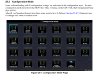
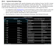
Probably the quickest way is to this is to unmount the PFD, and jiggle the wires to the PFD.. then to the ARINC box (silver box, larger connector), then to the EMS box (mounted on firewall, smaller connector). See what fixes it. You can also go into Configuration Mode on the PFD (hold down MENU while turning it on). Under System Configuration, the PFD will show you the errors talking to each device on the bus.. which may be of limited use if the problem is so close to the PFD to begin with.. it'll show errors for every device. hah.

The CANBUS is white tefzel wire containing 2 conductors (and shield).. and its made with sections of wire going from device to device.. at each device, there is a solder splice with 3 wires: one from the previous device in the chain, a 2-3" stub going to this device, and a wire going to the next device in the chain. Actually, there's 2 splices.. one for the CAN HI wires, and one for the CAN LO wires (and some green wires to carry the shield from one section of wire to the next). Usually its these solder splices which didn't get melted fully. Once you locate the problem, we can talk about how to fix it.. likely involving heat shrink tubing, a heat gun or soldering iron and solder. This probably means removing the instrument panel cover skin to have better access to the wires to work on them.. which may mean removing the canopy to get to the one screw thats impossible to get to with the canopy still on.
 
Last edited:
CAN Failure

I have a factory built 2021 RV12iS with G3X IFR set up.

I am getting these CAS messages: AHRS, ADC, and EIS.

The following has failed: attitude indicator, air speed, altimeter. Just the pilot side pilot side.

Both sides: flap indicator, trim indicator, and engine gauges.

Happens at random, in flight, on ground. 80% of the time it does not work so I have grounded the plane. It is a flight school plane.

Any advice is appreciated.

Good Morning,

Did you have an SD card in the display at the time of one of the recent failures by change? That can help us understand the extent of the CAN failure. Typically if the entire bus is failing, the CAN wiring is being shorted to ground, this can be caused by a very small nick in the insulation of the CAN wiring. This can happen when a bad wire termination is generated at the time of installation, or over time if the wiring harness is subject to excessive vibration/wear.

Typically, you would have a backup RS232 path made from the GSU 25 and GEA 24 to the displays. This protects you against a complete CAN failure, and allows EIS and ADAHRS data to flow from those respective units to one display or the other. It sounds like the GSU 25 connection is made, but the GEA 24 connection is not.

Thanks,

Justin
 
Typically, you would have a backup RS232 path made from the GSU 25 and GEA 24 to the displays. This protects you against a complete CAN failure, and allows EIS and ADAHRS data to flow from those respective units to one display or the other. It sounds like the GSU 25 connection is made, but the GEA 24 connection is not.
/QUOTE]

Van's utilizes the redundant RS-232 path for the GSU25, but not the GEA24. This connection is made on the MFD, so I believe the symptoms being described are consistent with a can bus failure. There are a number of different things that can cause a failure like this, come of them simple some of them not, so it would be best to walk through this with either our support team or the G3X team.