pilot28906

Well Known Member
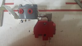
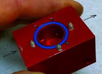
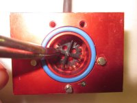
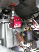
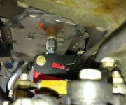
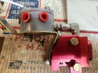
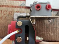
I have my red cube mounted directly to the spider divider on the engine with no cube bracket. I am at about 80 hours on the airplane and have had no problems with the red cube. It reads correctly and I am very happy with it. My question is are there others who have mounted in the same location without the red cube bracket who have had any trouble with this set up? I have the old style red cube mount but have not been able to make the fit work. I would like to see how many hours others have had with this setup and if they have had any problems with not using the red cube bracket mount.

Thanks
 
I assume you're using a flex hose or a steel nipple between the cube and the flow divider?

Some Airflow Performance purge valve installations mounted the valve body to the divider with a aluminum nipple. There was at least one fatigue failure of the nipple, which generated a bulletin to replace aluminum with steel.
 
Dan H. is correct.... critical lines, fuel, prop gov oil, oil cooler lines, on anything shaking, me personally steel.... Although there are countless AN aluminum fittings out there. I wonder if counterfeit or non aviation quality parts come into play?
 
We know of several early versions we did that have maybe 8 years of service----no telling how many hours. Steel components. No issues.

It was the forerunner of our bracket package that Dan helped to design from a concept idea from Chris Hrabe. We took the similar idea of the AFP purge valve and incorporated the FT60. Yes---it does work well. NO aluminum fittings.

Tom
 
Have you looked at the AS Flightlines red cube mount?
https://aircraftspecialty.com/rv-7.html

Yes, I have the first version and have not been able to make it fit correctly. Seems the angle of the engine bracket and the red cube bracket are different. Probably something I am doing wrong and may try again with it.

Yep give Tom a call. I was one of the initial installs and the geometry wasn’t quite right because of different brackets. You can still make it work with a shim or washers (like I still have) but I would ask Tom for a possible exchange.
 
New design

I had one of the early mounts. Tom sent me the latest version. I did need one shim but it mounted much easier.
Make sure the fuel line is the correct length. I moved the servo output to the top. It really shortened the fuel line.

Mount the fuel line to the cube. Install the mount with the bolt loose just a few threads turned in. Route the fuel line through the baffle. Slip the cube in place. Bolts slip in from forward toward aft. Add the washers and nuts. Tighten the mount bolt. This is the only tricky part. It helps to have several open end wrenches all bent differently. Finally, tighten the cube bolts then safety wire the mounting bolt.
 
FYI---WE've fielded a few calls and emails about the mismatch in our transducer bracket and the stock Lycoming 75009 bracket. Originally, I had purchased a 75009 bracket when we were designing our mounting bracket. WE matched the angles on the stock steel bracket, so our transducer bracket would nest together.

So, several of you have called and emailed about some dimension differences in the nesting angles. So----I took several of our Lycoming version brackets from the different production runs and test fitted them. So, that eliminated ( I thought) our bracket being the problem. So I ordered a 75009 bracket to see if there was a difference. Guess what-----there is. The downward angled from the flat area where the flow divider rests is different, by probably 10*, and the vertical bend dimension lower by maybe .200.

HAVE NO FEAR-----we have identified the fix to this. We obviously cant control the steel bracket and its bends, but we can control how our bracket is machined. We are holding off on the next production run of this version until we've solved this problem.

Just keeping you informed.

Tom
 
Only one small issue w this mounting

Mine is mounted using the Flightlines bracket and steel 90 fitting directly to the spider. My only issue that I've run into is a high fuel flow reading until I do a run-up. I'm thinking that I'm getting an air bubble in the red cube which is causing multiple readings on the sensor and resulting in higher than accurate measurement until I push fuel through it clearing the bubble. When I first start up - either after sitting for awhile, or a hot start, the fuel flow will read 6+ gph at idle until I do a runup and then will read a normal 1-2 gph at idle. So if anyone has any ideas on how fix my issue I'd be very open to suggestions. Anyone else have this issue?

https://share.icloud.com/photos/037E36ISFCLVSsRuuotbB8lvg

Other than that I highly suggest the flightlines bracket if you mount it here - its very robust and can alleviate a lot of stress from the steel 90. Having to do it all over again - I probably wouldn't mount it here given my issue w/ idle. Where to mount it is the next question - much longer threads on that one..... ;-)
 
Last edited:
Ryan----part of my theory of mounting it vertically at the flow divider was to force fuel and any air bubbles through the transducer to the flow divider.

Tom
 
Thanks all for the input.


HAVE NO FEAR-----we have identified the fix to this. We obviously cant control the steel bracket and its bends, but we can control how our bracket is machined. We are holding off on the next production run of this version until we've solved this problem.

Just keeping you informed.


Tom, Will you announce when the new version is ready?

Thanks
John
 
Ryan----part of my theory of mounting it vertically at the flow divider was to force fuel and any air bubbles through the transducer to the flow divider.

Tom

Yeah I agree but I can’t explain it. Maybe I should try a different cube???? Nobody else with this issue?
 
Last edited:
Hi John---yes we certainly will.
First pic is of our final design we came up with. See how our bracket nests 'nicely" with the 'then' 75009 steel Lycoming bracket.

2nd pic is of the bracket I got yesterday. See the gaps and mismatch in the aft bracket angles and dimensions.

While the 'new' 75009 bracket does fit the engines, the angle from the flat section where the flow divider sits, to the vertical drop to the case mounting boss is different, or at least different from the original 75009 bracket that we used to develop this. Yep----it was a Lycoming PMA bracket. So this means that our transducer bracket would not nest properly---like the original design.

I guess we 'could' make an integral 1 piece bracket with the flow divider mounting. But with the variations of flow divider/injector line configurations, and the high probability of the lines needing to be 'tweeked' to fit, I feel that its not a good idea. So Steve is going to reconfigure our bracket design to fit the 'new' 75009 Lycoming bracket--and we'll do some test runs before another production run.

Tom
 

Attachments

  • LYC FINAL BRACKET.jpg
    LYC FINAL BRACKET.jpg
    342.1 KB · Views: 253
  • 20230417_133109.jpg
    20230417_133109.jpg
    370.3 KB · Views: 184
Yeah I agree but I can’t explain it. Maybe I should try a different cube???? Nobody else with this issue?

I have one mounted vertically like yours, but bracketed to a sump bolt below the baffle. Perfectly accurate always, which makes me curious.

The internal exit port location would put only a very small volume of the rotor chamber above the port when vertical. I suppose it could trap a tiny bit of air at a low flow rate, but it seems unlikely.

Do you have a 2 psi spring in the divider, or a 4 psi?
.
 

Attachments

  • Fuel Flow.jpg
    Fuel Flow.jpg
    105.4 KB · Views: 162
  • Wheel in Chamber.jpg
    Wheel in Chamber.jpg
    68.6 KB · Views: 157
  • Cube.jpg
    Cube.jpg
    104.9 KB · Views: 194
  • Cube Bracket Installed.jpg
    Cube Bracket Installed.jpg
    94.4 KB · Views: 174
Dan and I worked on his install---hence the really custom short hose between the servo and the flow transducer. LOL---as all of you know, Dan is a VERY intelligent, methodical guy, and I know he considered the install configuration very carefully. And if his vertical install is fine, you can bet that if it wasnt, he wouldnt be running it. Dan helped us with the original concept of our bracket---and in effect did some of the flight testing on the vertical install. The 'Perfectly accurate always" statement coming from Dan just confirms what we knew from several years previously with installs on a former airshow teams aircraft.

Tom
 
Thanks Tom,
The 2nd photo look exactly like mine when I tried to install. Looking forward to seeing the new design.

As a side note; I have 80 hours on the red cube mounted to the divider and it is very accurate and no problems in these 80 hours.
 
I have one mounted vertically like yours, but bracketed to a sump bolt below the baffle. Perfectly accurate always, which makes me curious.

The internal exit port location would put only a very small volume of the rotor chamber above the port when vertical. I suppose it could trap a tiny bit of air at a low flow rate, but it seems unlikely.

Do you have a 2 psi spring in the divider, or a 4 psi?
.

Dan - thanks for the reply. I really like your mounting as well. I don't know if I'm 2 or 4 PSI - Its whatever AFP sends as stock - I haven't changed anything. I've reached out to Iflyei to ask them for ideas as I've talked to Tom and others on this thread don't seem to have the issues I'm having. Tom indicated out of all the other installs exactly like mine nobody is having this high reading on initial idle issue. The TS mounting is so clean and eliminates a hose so its quite simple - I just seem to be chasing a gremlin.

Thanks for the input - I'll let you know what I hear.

Ryan
 
Merhad and others---Yes originally the instructions were 2 inches of straight run into and out of the transducer. Over time, that has been resended some, UNOFFICIALLY. After several discussions with EI over installs at the flow divider, AND MANY of those installs flying all over the world, this configuration of install has proven to be a non factor.
With the 90* at the outlet side attaching to a straight nipple at the flow divider, the bend at the 90* is about 1.95 from the rotor in the cube. Its vertical orientation with the outlet at the high point, forces pressurized fuel and what little air bubbles to also be forced up and through the rotor cavity and onto the flow divider.

Tom
Well, well, well. FINALLY a breakthrough. After "finally" getting the needed data from Lycoming, Steve and I set out to make the necessary changes to our flow transducer bracket for the Avstar/Bendix/Precision flow dividers using the Lycoming 75009 bracket. Long story made shorter, there was an apparent change made to the bracket curve and downward angle of the steel bracket, that changed the aft side of ours. They didnt nest together properly anymore. This didnt affect its mounting to the engine, but changes our FT60 bracket. Lycoming DID change the lower hole that secures the bracket to the corresponding threaded boss on the case between the cylinders. So once we knew that it wasnt a design change, we changed our CAD drawings to accomodate that angle change. The newest 3D printed version confirms the correct modifications. So we plan to do another production run sometime after AirVenture on both the 'Avstar/Bendix" version and the AirFlow Performance version.
Sorry its taken such a long time, but it didnt make any sense to do a production run for a part that obviously wasnt going to fit. So here are the before and after pics so you can see for your self. I guess if there is a 'good' thing to come of this, it forced me to start learning CAD.

Tom
 

Attachments

  • new bracket differences.jpg
    new bracket differences.jpg
    370.3 KB · Views: 70
  • Final Bracket 7.9.2024.jpg
    Final Bracket 7.9.2024.jpg
    74.8 KB · Views: 69
Well, well, well. FINALLY a breakthrough. After "finally" getting the needed data from Lycoming, Steve and I set out to make the necessary changes to our flow transducer bracket for the Avstar/Bendix/Precision flow dividers using the Lycoming 75009 bracket. Long story made shorter, there was an apparent change made to the bracket curve and downward angle of the steel bracket, that changed the aft side of ours. They didnt nest together properly anymore. This didnt affect its mounting to the engine, but changes our FT60 bracket. Lycoming DID change the lower hole that secures the bracket to the corresponding threaded boss on the case between the cylinders. So once we knew that it wasnt a design change, we changed our CAD drawings to accomodate that angle change. The newest 3D printed version confirms the correct modifications. So we plan to do another production run sometime after AirVenture on both the 'Avstar/Bendix" version and the AirFlow Performance version.
Sorry its taken such a long time, but it didnt make any sense to do a production run for a part that obviously wasnt going to fit. So here are the before and after pics so you can see for your self. I guess if there is a 'good' thing to come of this, it forced me to start learning CAD.

Tom
Having a hard time finding the steel 90deg swivel fitting you guys are using with the spider mount installation. Anyone direct me to a source or PN? Bracket looks like the way to go, I'll keep an eye out for availability updates - Bendix version. THX
 
Having a hard time finding the steel 90deg swivel fitting you guys are using with the spider mount installation. Anyone direct me to a source or PN? Bracket looks like the way to go, I'll keep an eye out for availability updates - Bendix version. THX
LOL----the source is Aircraft Specialty Flightlines