SilverEagle2

Well Known Member
Friend
So...

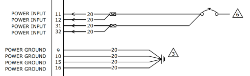
Planning my G3X GDU460 to AXIS GDU116 swap and need to take 1 power pin and turn it into 3. Same for the grounds (save 2 to 4).

I've done all sorts of splices in the past, but curious how you all like to do yours.

Is it better to splice closer to the GDU or the VP-X pin/Ground Buss (mind you, I am also going from 22AWG to 20AWG for all)?

Splicing at the GDU means the wire count in the bundle effectively remains the same. Doing it at the Power Buss/Ground Buss end means up to 5 more wires travelling the harness length.

Is it better to do an "inline" splice by opening up a small section/break in the insulation past the pin and soldering in a second wire with a solder sleeve, OR use butt splices and crimped individual wire segments staggered?

Like some thoughts from the brain trust.
 
Last edited:
Suggestion: whichever method you choose, it's a good idea to ensure the splice is visible on the outside of the bundle, easy to inspect. I hate "buried" splices since those are the ones that invariably go awry.

If it were me I would use a hermetically sealed solder splice 1:3, staggering the splice locations for power and ground, but keeping them fairly close to the terminating connector. All of this, of course, is predicated on your existing single wire meeting the current carrying requirement of the combined loads from the three terminating connections.
 
This is how I do it: Make sure your wire gauge is adequate of course, and use good crimpers. The JD ready version of the TE Connectivity Environmental Splices work fine. They have different sizes for different guage wire. You'll have to use a larger splice when doubling up wires. But done properly it is a very good splice. The alternative is a western union splice which mechanically looks the same, but involves a soldering iron and regular heat shrink. I do this when the install guide says the LRU has 2 power inputs on one breaker. Garmin and Dynon both do this. I would never do this when the wiring plan calls for separate breakers.

55412053255_70db8fd471.jpg
55411857329_1b2b230dc0.jpg
55411690726_b67f2a2218.jpg
 
Last edited:
Garmin has nice video's on their youtube page showing options with butt splices and fanning it out and solder/heatshrink. My plan was to use a single sufficiently large wire from the vp-x to the GDU and then split it out. Granted reviewing the manual, it looks like it suggests 2 wires from the breaker, which would technically be the VP-X... so may split the difference and do that.

1784743532957.png
 
Garmin has nice video's on their youtube page showing options with butt splices and fanning it out and solder/heatshrink. My plan was to use a single sufficiently large wire from the vp-x to the GDU and then split it out. Granted reviewing the manual, it looks like it suggests 2 wires from the breaker, which would technically be the VP-X... so may split the difference and do that.

View attachment 123943
So the 20AWG "Main" is sufficient to carry the total load from the 3 (or 4 branches)...no issues there.

Since I have a backup battery taking up 1 of the 4 pins...mine is more along the lines of this config.

1784747464331.png

Appreciate the ideas thus far. Still curious whether being closer to the VP-X pin vs. the GDU pins is advantageous/preferred. My harness has a mix of both.
 
So the 20AWG "Main" is sufficient to carry the total load from the 3 (or 4 branches)...no issues there.

Since I have a backup battery taking up 1 of the 4 pins...mine is more along the lines of this config.

View attachment 123945

Appreciate the ideas thus far. Still curious whether being closer to the VP-X pin vs. the GDU pins is advantageous/preferred. My harness has a mix of both.
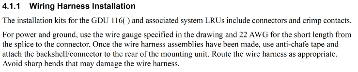
I'm wiring mine right now, so I'm going over the manual pretty deep and found this which suggest closer to the GDU.
1784748440857.png
 
Assuming wire gauge is adequate as mentioned, I stagger splices. I use the Ideal StripMaster tool to open the insulation in one or more places as needed. A window long enough for the splice is adequate. I slip on solder Splice and heat shrink where required. Wrap the Splice around the bare wire. Heat the solder Splice. Move the heat shrink over and heat that. Makes for a nice smooth bundle. I did it mainly for grounds.
 
From an electrical safety perspective, if you are branching from one big wire into several smaller-gauge wires, those smaller-gauge wires need to be as short as possible. The reason is that your fuse/breaker is matched with the thicker wire and if one of the thinner wires were to short to ground they could theoretically catch on fire before tripping the breaker/fuse.

So if there is a 7.5A breaker/fuse and a 20AWG wire, then that splits into several 22AWG wires, you want those 22AWG wires to be short and well protected.
 
From an electrical safety perspective, if you are branching from one big wire into several smaller-gauge wires, those smaller-gauge wires need to be as short as possible. The reason is that your fuse/breaker is matched with the thicker wire and if one of the thinner wires were to short to ground they could theoretically catch on fire before tripping the breaker/fuse.

So if there is a 7.5A breaker/fuse and a 20AWG wire, then that splits into several 22AWG wires, you want those 22AWG wires to be short and well protected.
Agreed...why I am just going to stick with 20AWG throughout.