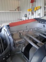
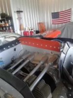
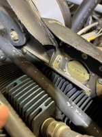
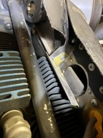
Is there any benefit, or has anyone tried adding additional baffling as shown in the pic below? This is just a mock up, and the final would seal around the lifter tubes and the fuel injector lines and extend up to the plenum. I have not done a flow analysis of this idea yet, but just looking at it, it seems that it would help eliminate the turbulent air over the center portion of the engine, and direct the airflow where it needs to go. Carbon fiber with high temp epoxy would work. Is there any data concerning the temp of the cylinders at the base?? It wouldn't be nearly as high as the cht of course.
1000007292.jpg
1000007293.jpg
 
Jabiru aircraft engines do it similiar to what you are proposing. Works for them!
 
Just noticed that the OP is asking about an IO390 on a -14. Mine has stock cowl and baffling around the EXP119 engine. My CHT's are never a problem. I rarely see the hottest (#2) cylinder touch 380 degrees, in climbs.
Do other -14 fliers see high CHTs?

Bill
 
A friend, one that is no longer with us, once told me that he did a two plenum arrangement like the one shown in post #3 on his RV-3 and had poor cooling. One side was always hotter than the other during climb. When he linked the two together, the cooling improved. Told me that it was not worth the extra work.
 
I have not done a flow analysis of this idea yet, but just looking at it, it seems that it would help eliminate the turbulent air over the center portion of the engine, and direct the airflow where it needs to go.

Inlet turbulence is bad for pressure recovery (the conversion of dynamic pressure to static pressure), but In any heat transfer from mass to fluid, turbulence is beneficial. And don't kid yourself...the case is hot, the air is not, so it is a cooling path in addition to the cylinder fins and oil cooler.

Carbon fiber with high temp epoxy would work. Is there any data concerning the temp of the cylinders at the base?? It wouldn't be nearly as high as the cht of course.

I asked that very question in conversation with a sharp friend at Lycoming. Not measured in recent times.
 
In consideration of what @DanH said in #8, perhaps another idea would be to move that "divider plate" (splitter plate, diverter plate, .... dinner plate) to the area between the cylinder heads and cylinder barrels and extend it all the way forward to the inlet ramps.

Have you already flown and collected temperature data?

edit: also figure out where to put a "case temp" sensor on the case in a couple of locations - fore/aft/left/right --- just to see what's going on before & after.
 
I have a datapoint that may be of insterest to some.

Larry Vetterman built an experimental cub ~2014. Below is a link to a thread on supercub.org If you jump to post #21 you'll see carbon fiber plenums on each side. Its just a very simple quick install, and mating up with his nosebowl intake. Post #21, and #24 has the photos. in post #31 Clint gives a report of the outcome of these on Larry's cub.

I kick myself for not pursuing those a few years ago. I don't know what happened to this. That is another data point....its was installed, and it did not take off. When my build is done, this is something I'd enjoy experimenting with.
 
It will "work" but you are losing VOLUME. I think a typical single plenum with full volume over the crank case is better than two isolated smaller plenums, my opinion based on physics. The more volume better is my assumption. Will it make a big difference? Don't know. Turbulence is all over and the area over crank case is not an issue. The whole idea of the round inlets with airfoil shape internal curves is to recover the most air without turbulence. Once it gets to jugs #1 and #2 it is starting to hit cylinder fins, pushrod tubes, turning corners to go trough the top of plenum to lower cowl...

Second reason to leave it one big happy plenum, airflow going in the LEFT and RIGHT cowl inlets, due to prop airflow and other factors is NOT even from left to right. Having one open plenum may produce better cooling pressure balance on both sides?

You are already flying with this configuration leave it. FUEL INJECTION? Will it keep fuel cooler, with distribution spider not under same roof as the cylinders? Speculation, I don't think it can be measured. I have seen separate L& R plenums has been done on RV's and of course many other planes. I thought about it. I decided to not reinvent the wheel and be a lemming and built it per plans (not really per plans).

I have round airfoil shaped Dave Anders cowl inlets in modified stock cowl. The engine baffle is a dog house (dedicated cover) vs soft seal against top of cowl, like you have, common non plans configuration modification. Anything you do to keep air from leaking and not doing work to cool is lower (cooling) drag. IF YOU DO THIS TAKE DATA BEFORE AND AFTER, TEMPS AND SPEEDS and POST IT...
 
Last edited:
It will "work" but you are losing VOLUME. I think a typical single plenum with full volume over the crank case is better than two isolated smaller plenums, my opinion based on physics. The more volume better is my assumption.....
All "other" things being equal;

Neither the inlet area nor the ultimate flow path through the cylinders changes, The delta volume between the two approaches wouldn't measurably change the pressure recovery because of the latter would ultimately limit V. While the split plenum may manage the available cooling air "better", I wouldn't expect overall airflow to change. Of course, if the original plenum was a poor design then the new approach may improperly receive the "credit".
 
Here is a photo of what I'm proposing. Pilot side is the same setup. I'll get another "real world "photo once I get the aluminum back from being laser cut. It will extend nearly to the plenum in the vertical direction, leaving about 2mm between the upper portion of the divider and the plenum. Had originally considered attaching the top of the divider to the plenum, but there is movement, expansion, of the plenum in flight. So there will be support at the intersection of the plenum and the divider, but it will be able to move vertically. Space around the lifter tubes and fuel lines, and an intimate fit fore and aft, coming into contact with the baffling.

I found it interesting that there is no collected data out regarding the temps at the base of the cylinders on air cooled engines. How hot does it get?? Going to put some temp probes there to find out.

I'll model everything soon and do a finite element analysis, fluid flow analysis. It won't be definitive, but at least it will give an idea of direction and volume. Air flow is an interesting animal, it follows physics of course but is not necessarily intuitive. I did a fluid flow simulation and posted results here for the air inlets on a sam james cowl. Results were not great. DanH pretty much indicated that to improve them would necessitate a redesign of the inlet placement (if I remember correctly).

To address some of the questions and observations, you may be correct and it won't make any difference. Might even make things worse. Is turbulent airflow over the crankcase a good thing? Any speed gains without it? Gonna find out. If it is of no benefit, easy enough to remove it. But it sure is way fun to experiment and try something different :)
 

Attachments

  • PXL_20240529_182537438.jpg
    PXL_20240529_182537438.jpg
    4.9 MB · Views: 85
Jimmy from JB Aircraft Engines sent me these pics. They were from one of his customers. A couple of his customers have done this and report positive results.
 

Attachments

  • Resized_20200927_083022_5214.jpeg
    Resized_20200927_083022_5214.jpeg
    54 KB · Views: 104
  • Resized_20200927_083014_6127.jpeg
    Resized_20200927_083014_6127.jpeg
    29.1 KB · Views: 105
I’ve done it similar to above after seeing that aircraft on display at JB’s booth at SNF. Helped even out temps across the board.IMG_1406.jpeg
 
I’ve done it similar to above after seeing that aircraft on display at JB’s booth at SNF. Helped even out temps across the board.View attachment 63796
I might be full of hot air....... :ROFLMAO: :LOL::LOL::ROFLMAO:.....but from an engine cooling standpoint, this makes more sense than isolating the case from the cooling airflow with the cylinder base dams. Seems like the engine would benefit from cooling airflow over the area where the cam shaft sits. Would it make a difference? 🤷‍♂️
 
An old time A/P A/I buddy has recommended the single center baffle in the past-----only issue I can think of is the oil cooler steals a lot of air from one side.
 
An old time A/P A/I buddy has recommended the single center baffle in the past-----only issue I can think of is the oil cooler steals a lot of air from one side.
Unless you're me. I have to block most of the oil-cooling air intake off. Two dams: one for 70 degrees and below; one for 70 degrees and above (average flying temperature). And that is with the cooling gait closed! 🤷‍♂️
 

Attachments

  • img.834.jpg
    img.834.jpg
    114.4 KB · Views: 51
  • img.839.jpg
    img.839.jpg
    27.2 KB · Views: 52
  • img.836.jpg
    img.836.jpg
    134.7 KB · Views: 53
Just noticed that the OP is asking about an IO390 on a -14. Mine has stock cowl and baffling around the EXP119 engine. My CHT's are never a problem. I rarely see the hottest (#2) cylinder touch 380 degrees, in climbs.
Do other -14 fliers see high CHTs?

Bill
Same but I normally see nothing higher than 350 F even in hot Florida summers. LOP drops to 320 F. Stock set-up and no added "dividers". I've been told angle valve engines CHT's run cooler and oil temps a little warmer. Seems to be true.
 

Attachments

  • Screenshot 2024-05-30 190509.jpg
    Screenshot 2024-05-30 190509.jpg
    102.4 KB · Views: 15
Maybe a single divider is better, or maybe it is just easier to fabricate. The inner engine case, where the crank resides, is receiving a constant supply of oil, and oil starts to break down at around 275 F (varying data......). So the question still remains, how hot are the cylinder bases, and in addition, does the engine case need air for cooling? I wouldn't think the case is getting much over 250 F, and if it depended on air cooling, why no cooling fins? Be easy enough for the manufacturer to add them. In any case, I'll try my design with multiple temp probes and compare it to a baseline. The idea could end up being an Edsel.....
 
Just noticed that the OP is asking about an IO390 on a -14. Mine has stock cowl and baffling around the EXP119 engine. My CHT's are never a problem. I rarely see the hottest (#2) cylinder touch 380 degrees, in climbs.
Do other -14 fliers see high CHTs?

Bill
My -14 always runs cool. On a hot summer day I see the hottest cylinder reach 380 on climb out. At cruise, LOP, CHT’s run in the low 300’s. In winter they rarely exceed 300. My CHT’s are all within 10 degrees of one another. I removed the air dam from in front of cylinder #2 and shortened the one in front of #1.
 
I was speaking with Don Rivera and this subject came up. Don has seen the plenum divider installation before. With fuel injection, it tends to reduce cooling around the flow divider, which can introduce a variety of problems. Advises against.
 
I was speaking with Don Rivera and this subject came up. Don has seen the plenum divider installation before. With fuel injection, it tends to reduce cooling around the flow divider, which can introduce a variety of problems. Advises against.
Thank you Dan for researching this and passing along the info! Good to know. Every modification seems to be multi dimensional in its effects, and sounds like this one is no different.