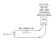
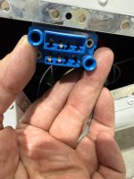
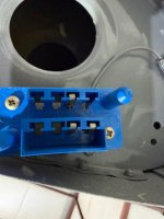
Quick electrical question: left wing nav/strobe lights not working. I have the wings off for annual inspection. Before removing the light, I checked the fuselage connector. Three contact points. Ground is good. I’m guessing the other two are for the lights and the stall warning. With the light switch on, I’m getting 12.5 V on one contact and 10 V or so on the other. I had assumed I would get 12 V on both. Is this normal?


 . If he has the D180 as pictured, he doesn’t have the the AV 5000.It would have Van’s earlier RV 12 module. One of my lights quit and it was the light, around $1,000 for the pair if I remember.