Clayvt

Well Known Member
Patron
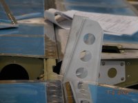
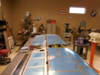
I am fitting up the horizontal stab for drilling but seem to have an issue.
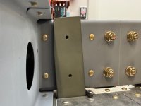
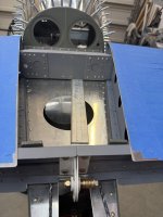
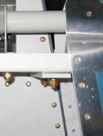
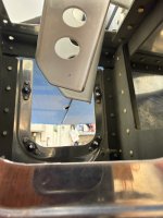
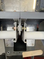
Just eyeballing before even measuring, when I clamp the rear spar to the vertical bars the leading edge is nowhere near centered. To get it centered while still making contact with the vertical bars it has to shift left so much that it runs into the horizontal stab skin and still needs to go more.

If I pivot the leading edge to get them roughly centered, then I have a gap on the left vertical bar about 3/16”.

Any guidance or help would be appreciated. IMG_8709.jpegIMG_8710.jpeg
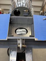
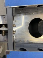
And yes, I will be going back and re squeezing all the rivets on the stab.
There are a few I am going to replace as I just don’t like the look of them. Can really tell I was at the beginning of the learning process with this!
 
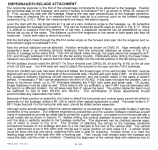
Suggest you go back and RE-READ the rigging instructions in the manual. The RV-6 required to square and align the H.S. with the airplane. On the RV-6, shims may be necessary between surfaces so that stress is not introduced into the airframe when bolts are torqued. Image attached is from the RV-6 manual.
 

Attachments

  • Screenshot 2026-07-02 at 3.24.25 PM.png
    Screenshot 2026-07-02 at 3.24.25 PM.png
    989.2 KB · Views: 20
It looks to me from your pics that your HS is not sitting in its final location exactly correct. If the centerline on your forward spar web on the HS is correct, it looks to be slightly right of the Cl on the aft fuselage bulkhead. Also looks like it might be slightly too far forward based on the observation that the vertical bars attaching the HS aft spar look like they might be bending slightly forward. The two spars on the HS do not sit flush on that aft deck. My forward spar is 1/8” above the aft deck. The aft spar a bit more. Keep in mind, two critical measurements are an equal distance from the HS tip to a common perfectly center location on the fuselage (or wingtip if was installed), AND a correct angle of incidence. Those two precise locations will make what you’re seeing look different.
Easiest first adjustment though is to move the HS slightly to the left.
 
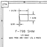
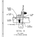
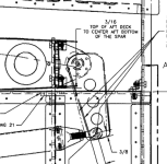
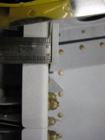
Don't forget about the F-798 shims and the rear spar sitting 3/16" off the deck before you drill.

May not fully solve your problems... but they are important to include. Check drawing 27A for the details.
 
Suggest you go back and RE-READ the rigging instructions in the manual. The RV-6 required to square and align the H.S. with the airplane. On the RV-6, shims may be necessary between surfaces so that stress is not introduced into the airframe when bolts are torqued. Image attached is from the RV-6 manual.
there is no mention of shimming (other than the 1/8” shims under the front spar in the 7 manual.
 
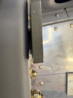
To get it square and on centerline it had to shift left so much that the right vertical bar interferes/overlaps the flange of the inboard rib of the stab.
And there is still a gap on the right vertical bar.
IMG_8715.jpegIMG_8714.jpegIMG_8713.jpeg


Where it is sitting right now, it has that 1/8" spacer up front (just temp, to mock it up not the final two spacers under each side) and the 3/16" in the rear. The stab is squared/equidistant to the firewall on each side.
This is how its sitting with the interference and gap.

The plans have you locating and drilling the holes without the spacers in place and putting them in after to match drill.
 
Last edited:
there is no mention of shimming (other than the 1/8” shims under the front spar in the 7 manual.
Not sure if it's in the manual or the plans, but there are two 1/8" shims under the forward spar and a 3/16 temporary spacer under the aft spar. That's for starters. Then the incidence is measured and shim(a) may need to be added forward to get the tooling holes level to the longerons. Then measurements from a central fuse reference to each tip to get sweep equal. Then, if that's not enough, the forward hole has almost zero room for error through the longeron. It's well documented here. Measure a thousand times before drilling then drill those two hole small and measure edge distance again. Better safe than...

Personally, the VS and Rudder were more time consuming.
 
Not sure if it's in the manual or the plans, but there are two 1/8" shims under the forward spar and a 3/16 temporary spacer under the aft spar. That's for starters. Then the incidence is measured and shim(a) may need to be added forward to get the tooling holes level to the longerons. Then measurements from a central fuse reference to each tip to get sweep equal. Then, if that's not enough, the forward hole has almost zero room for error through the longeron. It's well documented here. Measure a thousand times before drilling then drill those two hole small and measure edge distance again. Better safe than...

Personally, the VS and Rudder were more time consuming.
Larry is referencing DWG 27A.

Screenshot 2026-07-02 at 7.14.36 PM.pngScreenshot 2026-07-02 at 7.14.47 PM.pngScreenshot 2026-07-02 at 7.15.07 PM.png
 
Mine wasnt too dissimilar on first fit up.

IMG_0130.jpeg

Ended up shimming with what appears to be 063 or so.

IMG_5216.jpeg

Almost 20y to the day…
 
Thank you. Ill put a call in to vans too but I was mainly wondering if it was ok to have that gap and fill it.
So long as the stab is centered and square.
No worries.
It’s been a long time but I have a feeling that they said that small a gap was fine to bend the 711Cs. Or to shim.
I’d be curious to see what they say.
 
So Vans says a shim is ok.
They also said I could square up the front then let the bolts on the rear draw bars to the spar. I don’t like the sound of that. I don’t want to have them under tension.

But now I have a new issue!
Again, just mocking up to see how everything will work out.
With the 1/8th shims up front the book says to put 3/16 under the rear spar to set the incidence and to verify by comparing the tooling holes on the inboard ribs to ensure it’s level to the deck.
My tooling holes are nowhere near close.
The front tooling hole looks on centerline but the rear is off center.

Anyone think using the skin would work?

Unless I use the nose rib hole?
I thought I read someone’s build log where they were told to not use the nose rib.

The plans aren’t exactly clear on this.
IMG_8737.jpegIMG_8736.jpeg
 
I recall measuring the tooling holes and found one, maybe two not centered. I ended up using measurements to get the incidence correct. It took forever first to figure out why then get it right. Plane flies straight so I guess I got it right.
 
Ok, got the H stab and V stab mounted and moving on the the elevators.
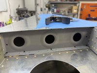
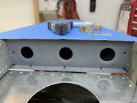
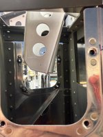
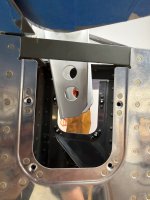
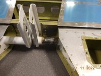
When I follow the dimensions for the pushrod hole on the aft most horn, it appears the hole on the fore horn will be way too close to the rear edge.
“maybe” just about 1.5D for edge distance, not 2D

Has anyone moved the hole forward a bit towards the bent flange? Or how can I fix the position of the fore horn?
The trailing edge is within 1/16th btw elevators with the counterweight clamped.


IMG_8753.jpegIMG_8754.jpegIMG_8755.jpegIMG_8756.jpeg
 
Last edited:
I would say edge distance is a guide line not an absolute, plus it’s usually more critical on aluminium parts due to the softness of the material. If you’re looking at 1.5D in thick steel weldments like these then I think it’s fine.

If you’re worried I would run it past Vans, but I’m 90% sure they will say build on.
 
The only issue you may see is the control rod hitting the weldment. You could always get a longer bearing. It's steel. Edge distance is less of a problem.
 
Ok, got the H stab and V stab mounted and moving on the the elevators.
When I follow the dimensions for the pushrod hole on the aft most horn, it appears the hole on the fore horn will be way too close to the rear edge.
“maybe” just about 1.5D for edge distance, not 2D

Has anyone moved the hole forward a bit towards the bent flange? Or how can I fix the position of the fore horn?
The trailing edge is within 1/16th btw elevators with the counterweight clamped.


View attachment 123447View attachment 123450View attachment 123449View attachment 123451
This offset is not uncommon. You just have to work with it.
When drilling for the control tube heim, I clamp each elevator in position at the counter weight to the HS so that they are perfectly lined up.
Then, I make a spacer, about 1” square at least, to go between the horns with a really snug fit out of aluminum, or hardwood would do. Then drill a perfectly perpendicular hole with a drill press in this spacer. I go with size 40 drill to start.
With the elevators clamped in place, drill one horn with a size 40 bit.
Slide in the spacer and use a 12” bit to drill through first horn, through thr spacer you made and then through the other horn. This will give you a perfectly square hole.
Once you have done this, gradually enlarge the hole till you get to 3/16.
This will give you perfectly lined up elevators.
If you want to verify along the way, when you get the hole drilled for a size 8 machine screw you could bolt it together with a #8 screw and nut and release the clamps to verify the elevators are aligned. The spacer you made acts as the heim and washers you will eventually install.
Even though the horns don’t match up perfectly, you will just grind the stops to match the offset horns.
The important thing is to get the elevators aligned with the HS.
I’ve done this a bunch of times on different kits that I have purchased or repaired for folks and it works well for me. I’m sure other folks have different methods but this is simple and works.
 
The important thing is to get the elevators aligned with the HS.
Agree with your entire process here except this one - unless I’ve misinterpreted this.

The important thing is to make sure the trailing edges of the elevators line up with each other. That’s more important than the individual elevator counterbalances aligning with the HS (which will give you mini tail ailerons unless your elevators are perfectly twist free)
 
Agree with your entire process here except this one - unless I’ve misinterpreted this.

The important thing is to make sure the trailing edges of the elevators line up with each other. That’s more important than the individual elevator counterbalances aligning with the HS (which will give you mini tail ailerons unless your elevators are perfectly twist free)
Richard
Yep I agree. Even an off kilter trim tab can make some difference so it’s good to check all those things. This is the stage to correct any twists that you can.
Van used to say if everything is within 1/4” you are good to go!. Maybe a little tongue-in-cheek, but it’s tough to get everything perfect.
 
I choose another approach to correct a misaligned elevator bell crank. Since both elevators were built, I opted to cut the offending bell crank arm off along the horizontal extension, machine and insert an internal sleeve, re-clock the bell crank, rosette weld each side in four places, then butt weld the original cut line. Probably a bit over kill, but it's hell for stout and the elevators are perfectly aligned.

Chuck Brietigam
RV-6XXL
 

Attachments

  • DSCN1262.jpeg
    DSCN1262.jpeg
    271.7 KB · Views: 22
  • DSCN1253.jpeg
    DSCN1253.jpeg
    188.1 KB · Views: 22
  • DSCN1261.jpeg
    DSCN1261.jpeg
    244.1 KB · Views: 23
I went ahead and drilled through (making sure to keep the horns parallel with a spacer) and it came out well.
Now I just have to trim some of the up stop to allow for more elevator travel.
 
Thank you for the replies and assistance!

I’m just an amateur over here trying to figure this stuff out!
 
Yep, "education or recreation" . . . I think there are a lot of us that are first time builders and haven't seen how the project at hand will turn out, so we just don't know. I've spent a lot of time staring at the plans and when I finally put it together, it wasn't as complicated as I thought. Other times (usually after making a mistake) I've thought of throwing in the towel.
This forum has been so invaluable, much gratitude for those that unselflessly donate their time posting their knowledge and experience!