TASEsq

Well Known Member
Patron
I am hoping someone else has come across this.

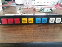
I was planning to use the functionality of the GEA24 to ground 2 lights for master warning / caution. This works by going low on pin 44 or 45 to give a ground to turn the lights on.

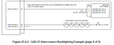
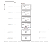
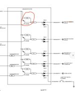
I wanted to send these through the GAD27 PWM dimming circuit to make the lights dimmable at night - however, i find that the GAD27 circuit dims by pulsing (PWM) the GND side of the circuit - i need to send power to the lights, then connect the ground to the GAD27 to dim.

These 2 devices obviously won’t work together! Has anyone else come up with a solution for this?

I could have a dedicated dimmer pot which adds resistance on the positive side of the master warning / caution lights but this seems silly. I was hoping to have it go through my "instrument lights" pot, which would dim all the cockpit indicators (as well as control the DC circuits to dim the screen bezels etc).

Otherwise, maybe i can use a "BRIGHT/DIM" switch which adds a resistor of a fixed value onto the power supply side of master warning / caution lights. Could add a “test” momentary as well. Or just live with them being bright?
 

Attachments

  • Screenshot (89).png
    Screenshot (89).png
    19.5 KB · Views: 33
  • Screenshot (90).png
    Screenshot (90).png
    17 KB · Views: 38
Last edited:
I also sent this question to the G3Xpert email address but I haven’t heard anything back after a few days. Will post the response here if I get it.

Am I the only person who’s ever wanted to do this?
 
I think you have exhausted all the options in your 1st post.. There have been more than one requests in the past already with no real elegant solution on this.
 
Warning light dim

Trent,

I am finishing up a dual G3X install and this is what I have done.

I used 2 12v LED push button lights. I used the red and yellow ones.

https://www.amazon.com/Baomain-Butt...698724082&sprefix=12v+led+push,aps,508&sr=8-5

And these as the back socket.

https://www.amazon.com/dp/B01H5C5CB2?psc=1&ref=ppx_yo2ov_dt_b_product_details

I put a 500 ohm 1/4 watt resister in-line with the + LED, and pin 50 on P244 of the GEA24. I then put a SPST micro toggle switch over the resistor to short out the resistor for bright, and when the switch is open, that will dim the LED.

I then wired up another ground through the N/O part of the switch, so the push button part of the LED will be a push to test.

Easy peasy.

Good luck.

Brian
 
Use a PNP transistor in an emitter follower configuration to supply power to the caution lights. Control the follower with the GEA24 (ground turns the follower ‘on’.) Connect the dimmer on the ground side of the lights as usual.
 
Dimmer circuit

What BobTurner said. See the Annunciator PCB circuit on p. 5 of this schematic for how I plan to handle dimming for the master caution/warning and other indicators:
https://vansairforce.net/community/showpost.php?p=1707050&postcount=76

The master caution/warning indicators I'm using are 12V so you'll need an extra resistor for a regular LED that doesn't already have one built in. If your indicator draws a lot of current, you may need a different transistor.

Disclaimer - I haven't built the circuit yet so I'd advise testing it on a breadboard first.

-Bob
 
Just a couple of thoughts on your issues. While I have dimming of my annunciator indicators I decided that my Master Warning and Master Caution will always be at full brightness. With the later SW releases you can extinguish these lights if desired, but you need to have at least one switched input to do that. I used the Honeywell indicator model with an internal switch so if the light goes on I can push it to turn it off. This was a relatively recent update in the SW so I had to make that change to my indicators.

I have several annunciators in addition to the G3X outputs so I designed a driver printed circuit card to allow driving of these lamps. It also includes a lamp test function. It's easy to get off track on side projects I'm afraid. As Bob mentioned a simple transistor circuit can do the trick of driving lamps if needed. My driver board is essentially that for multiple lights with the test function added.
 

Attachments

  • annunciator.jpg
    annunciator.jpg
    246.3 KB · Views: 31
  • annunciator_controller.jpg
    annunciator_controller.jpg
    396.5 KB · Views: 23
Use a PNP transistor in an emitter follower configuration to supply power to the caution lights. Control the follower with the GEA24 (ground turns the follower ‘on’.) Connect the dimmer on the ground side of the lights as usual.

That’s a great idea. I just finished learning about optocouplers and transistors in order to make an arduino (which can only sink 10ma or something on its pins) work as a 12v relay driver for a smoke pump.

What BobTurner said. See the Annunciator PCB circuit on p. 5 of this schematic for how I plan to handle dimming for the master caution/warning and other indicators:
https://vansairforce.net/community/showpost.php?p=1707050&postcount=76

That is an elegant solution. I like the idea greatly. It additionally overcomes an issue I was having with the 20ma max sink on the gea24 pins. My lights were more than this so I was going to use a resistor to lower the current draw (and unfortunately the brightness). Your design I can run them at full tilt and dim them through the gad27.

Can I ask a couple of questions about your design:
1. What’s the purpose of the 10k resistor connecting power to the transistor base? Is this a pull-up resistor to ensure that when the gea24 isn’t grounded, the transistor will not activate? Is it likely that it would activate if the base were left floating?

2. For your test circuit, you’ve used some diodes to isolate the push to test ground from the gea24 ground. Since the gea24 pin floats when there is not a warning/caution active, is it a problem is this pin sees ground when you press to test?

Thanks for taking the time to share your design. I really like it. Time to look at getting a pcb printed I reckon. For the smoke system I just used an arduino with a prototype board. But I reckon I can do better this time!!
 

Attachments

  • IMG_7470.jpeg
    IMG_7470.jpeg
    176.3 KB · Views: 46
1. Yes, the 10k is there to make sure the transistor is off when the gea is not grounded. When the gea is open, you really don’t know what tiny currents might flow (the transistor has a lot of gain) so the 10K to power makes sure that’s where you are.
2. Without the diodes, an ‘on signal’ from the gea to one light would flow thru the ‘push to test’ line to all lights, and they’d all come on. ‘Diode isolation’ is the term often used.
 
2. Without the diodes, an ‘on signal’ from the gea to one light would flow thru the ‘push to test’ line to all lights, and they’d all come on. ‘Diode isolation’ is the term often used.

Ah, yes of course. Thank you.

I’m going to shamelessly steal your circuit - good way to learn how to print a pcb. Might even combine it with my dimmer pots to give them some support and make wiring them up easier.
 
That’s a great idea. I just finished learning about optocouplers and transistors in order to make an arduino (which can only sink 10ma or something on its pins) work as a 12v relay driver for a smoke pump.


That is an elegant solution. I like the idea greatly. It additionally overcomes an issue I was having with the 20ma max sink on the gea24 pins. My lights were more than this so I was going to use a resistor to lower the current draw (and unfortunately the brightness). Your design I can run them at full tilt and dim them through the gad27.

Can I ask a couple of questions about your design:
1. What’s the purpose of the 10k resistor connecting power to the transistor base? Is this a pull-up resistor to ensure that when the gea24 isn’t grounded, the transistor will not activate? Is it likely that it would activate if the base were left floating?

2. For your test circuit, you’ve used some diodes to isolate the push to test ground from the gea24 ground. Since the gea24 pin floats when there is not a warning/caution active, is it a problem is this pin sees ground when you press to test?

Thanks for taking the time to share your design. I really like it. Time to look at getting a pcb printed I reckon. For the smoke system I just used an arduino with a prototype board. But I reckon I can do better this time!!

This works well, I do this routinely to dim LED annunciator lamps that are ground-sensed. PWM on the positive end, sensed signals on the ground end. I even do both--- PWM on both sides (required for my OnSpeed installation).

If you need only one or two circuits, it's easy to build on a solder-cup DSUB connector. I prefer using 2N4403 transistors, they will drive more loads.

Vern
 
So i bit the bullet and sent some gerbers off to Guandong! Should have the boards back in a few weeks for only $40 including shipping. Minimum order quantity means i ended up with 15 of each of the boards! (15 warning light switching boards - up to 600ma per light, and 15 dimmer panel boards).

I realised after i sent them i chose the wrong potentiometer - i spent ages finding one which would mount strongly to the board, found a footprint for it, laid out all the boards, duplicated them and made proper edge cuts etc, only to realise i had selected a potentiometer which did not have a panel mount bushing!!!

Doh.

Anyway, i have selected another one; this one panel mount. The pin layout is the same, but the board mount lugs are not. May need to just drill a couple of additional holes thought the board. Or design a whole new board maybe.. we will see. The new one is also top adjust, so the d-sub connector may need to mount to the back of the board, but i think this will be ok. Just different pin numbers.

I will load them with components and test them out - if anyone wants a board yell out and for postage costs i can send you one. The idea is the dimmer will mount using the 3 potentiometers, and the master warning panel will mount using #6 screws. Wiring goes into the boards using d-sub connectors.

The component list is here:
https://www.digikey.com.au/en/mylists/list/W31BTQ0ERJ
 

Attachments

  • Annunciator Panel.png
    Annunciator Panel.png
    249.3 KB · Views: 21
  • Circuits.png
    Circuits.png
    30.4 KB · Views: 15
Last edited:
Was too hot in the shed today - so i remade the dimmer board.

This time i will end up with 20 of them! :)

This board is designed around this dimmer, which has prongs to mechanically connect it to the board, and the board will be vertical behind the panel.

The 9-pos D-sub Connector will also click into the board, as well as be soldered and is on the backside of the board (so the pots will be on the aft side against the panel, and the dsub will be on the opposite side.)

Being vertical, and with the pots mechanically connected to the board (and smaller as well), they should be able to just be mounted in place using the pot mounting hardware.
 

Attachments

  • Annunciator Panel V2.png
    Annunciator Panel V2.png
    130.4 KB · Views: 16
  • Annunciator Panel V21.png
    Annunciator Panel V21.png
    114.4 KB · Views: 7
Last edited:
I’m using lights I picked up from Stein (pic below). For those that have used these, does the intensity warrant dimming?

If a mini toggle switch was used to dim, What value resistor should be used to decrease the brightness by 50%.
 

Attachments

  • IMG_1263.jpg
    IMG_1263.jpg
    169 KB · Views: 17
I’m using lights I picked up from Stein (pic below). For those that have used these, does the intensity warrant dimming?

If a mini toggle switch was used to dim, What value resistor should be used to decrease the brightness by 50%.

Just as a general rule, you’ll want lights dimmed at night so much that you cannot easily see that they’re on during the day. A lot more than 50%.