recapen

Well Known Member
Folks,
I am finishing the installation of a G5 (HSI) to replace the GRT MiniAP to get to a standard-size layout.
The instruments are installed and appear to check out on the ground well. I get an OAT indication and Heading indication which tells me that the Can-Bus installation is adequate. It drives my S-Tec30 properly on the ground with the Heading bug. I still need to do the Magnetometer calibration.

Meanwhile, I get a "Not receiving 429" error message even though the G5 switches from GPS to LOC when I toggle the switch on my 430W.
I have the latest software in my 430W and will be verifying the latest G5 software today.

Any thoughts on the 429 error messages?

Thanks,
 
Folks,
I am finishing the installation of a G5 (HSI) to replace the GRT MiniAP to get to a standard-size layout.
The instruments are installed and appear to check out on the ground well. I get an OAT indication and Heading indication which tells me that the Can-Bus installation is adequate. It drives my S-Tec30 properly on the ground with the Heading bug. I still need to do the Magnetometer calibration.

Meanwhile, I get a "Not receiving 429" error message even though the G5 switches from GPS to LOC when I toggle the switch on my 430W.
I have the latest software in my 430W and will be verifying the latest G5 software today.

Any thoughts on the 429 error messages?

Thanks

Did you install the GAD29 module?

The GAD 29/29B/29D is a light-weight, remote-mount unit that allows interface to IFR navigators such as the GNS and GTN series. The GAD 29/29B/29D has a 25 pin D-sub connector and a 9 pin D-sub connector. These connectors provide the following functionality:
• 2 Low Speed ARINC 429 Transmitters
• 4 Low Speed ARINC 429 Receivers
• 1 CAN Network Port
• *Analog Outputs
• *Excitation Pass Through *GAD29B/29D only

For the G5 Attitude and/or G5 DG/HSI installation the GAD 29/29B/29D will receive ARINC 429 data from the navigators interfaced and transmit that information onto the CAN bus to be consumed by the G5. The GAD 29/29B/29D can run on 14VDC or 28VDC. The GAD 29/29B/29D can also receive OAT information over the CAN bus to be converted to ARINC 429 data and transmitted to the navigators.

The GAD 29B/29D contains the same characteristics and function of the GAD 29 as well as providing autopilot heading and course datum to allow a G5 DG/HSI to be interfaced with autopilots. Reference section 5.22 and 5.24 for approved autopilot interfaces.

This is the wiring diagram needed to complete the install. Then go to page 136 in the install manual for the configurations setups. You need to go to the ADI, HSI, and the GNS430 sections for the required configuration settings.
 

Attachments

  • 183DFBA5-F24C-4426-ABE6-49D1DBA7C801.png
    183DFBA5-F24C-4426-ABE6-49D1DBA7C801.png
    325.8 KB · Views: 8
  • Garmin G5_STC Installation Manual.pdf
    4 MB · Views: 7
Did you install the GAD29 module?

The GAD 29/29B/29D is a light-weight, remote-mount unit that allows interface to IFR navigators such as the GNS and GTN series. The GAD 29/29B/29D has a 25 pin D-sub connector and a 9 pin D-sub connector. These connectors provide the following functionality:
• 2 Low Speed ARINC 429 Transmitters
• 4 Low Speed ARINC 429 Receivers
• 1 CAN Network Port
• *Analog Outputs
• *Excitation Pass Through *GAD29B/29D only

For the G5 Attitude and/or G5 DG/HSI installation the GAD 29/29B/29D will receive ARINC 429 data from the navigators interfaced and transmit that information onto the CAN bus to be consumed by the G5. The GAD 29/29B/29D can run on 14VDC or 28VDC. The GAD 29/29B/29D can also receive OAT information over the CAN bus to be converted to ARINC 429 data and transmitted to the navigators.

The GAD 29B/29D contains the same characteristics and function of the GAD 29 as well as providing autopilot heading and course datum to allow a G5 DG/HSI to be interfaced with autopilots. Reference section 5.22 and 5.24 for approved autopilot interfaces.

This is the wiring diagram needed to complete the install. Then go to page 136 in the install manual for the configurations setups. You need to go to the ADI, HSI, and the GNS430 sections for the required configuration settings.
I have the GAD29D installed - I would think that would have been a requirement to get the G5 switching from GPS to LOC when I toggle the switch on my 430W and driving my S-TEC-30 as indicated in my original post.... Learned something here.

The 430W GPS side is set up as Garmin GPS SDI 1 on input 1
The 430W NAV side is set up as Garmin VOR/ILS SDI 1 on input 2
I have tried SDI 2 and Common with no change

I used the info on Pg 116 instead of 136 as I have only the HSI installed...and I have a newer manual....

The unit is still at SW rev 8.00 as I don't have a small enough microSD to format as FAT... That's next.

Thanks for the education and confirmation!
 
Update...

Software version 8.44 has been loaded. Latest and greatest from the Garmin site.
No change to the initially reported issue after the G5 software upgrade.
I have noticed that setting the ARINC #2 input to none (instead of any flavor of VOR/ILS) prevents the error messages. The CDI button on the 430W for selecting GPS or VLOC now only deselects the GPS info on the G5.

Maybe I need additional education - what does the reference to SDI mean? There are references to SDI 1 and SDI 2 but nothing in the current manual clarifies the differences or when to use one instead of the other.

Selecting the Heading mode on my S-Tec-30 Autopilot allows for the heading bug to 'steer' the aircraft... At least during ground testing. Haven't flown it yet with all of these issues....

More learning experiences...
 
The ARINC 429 configuration page on the G5 will tell you which ports are receiving data, and which are not.
 
The ARINC 429 configuration page on the G5 will tell you which ports are receiving data, and which are not.
Please - more info on how to navigate to that information!
I am able to get to the 429 config page as that is where I have been working a lot lately - can't find anything related to port status.
 
Please - more info on how to navigate to that information!
I am able to get to the 429 config page as that is where I have been working a lot lately - can't find anything related to port status.
A green checkmark means receiving data.
 
I have a red X there - but still get info when I change the CDI toggle on the 430W - this is the contradiction....
This would be expected if you have a problem with the VLOC ARINC 429 interface between your GNS 430W and your G5/GAD 29. Make sure you have verified the wiring and followed *all* the configuration steps.
 
Maybe I need additional education - what does the reference to SDI mean? There are references to SDI 1 and SDI 2 but nothing in the current manual clarifies the differences or when to use one instead of the other.

Any additional info on my earlier request for learning about SDI (reposted here for convenience)?
The Source Destination Identifier (SDI) is used to identify the navigator sourcing the data. In a single navigator installation like you are using, you will always use SDI 1. In a dual navigator installation, one navigator is transmitting with SDI 1 and one is transmitting with SDI 2.

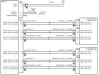
Here is an example dual GTN navigation installation diagram from the G5 installation manual that shows that GTN #1 is using SDI = 1 and GTN #2 is using SDI = 2.

G5 to GTN Dual NAV.png

Steve
 
The Source Destination Identifier (SDI) is used to identify the navigator sourcing the data. In a single navigator installation like you are using, you will always use SDI 1. In a dual navigator installation, one navigator is transmitting with SDI 1 and one is transmitting with SDI 2.

Here is an example dual GTN navigation installation diagram from the G5 installation manual that shows that GTN #1 is using SDI = 1 and GTN #2 is using SDI = 2.

View attachment 64214

Steve
Thanks Steve!
This is informative and helpful. Looks like the SDI markers are relative to the GAD-29...so adding a serial SL-30 (connected directly to the G5 not the GAD-29) would NOT change the SDI referencing. In my case, it is a GNS-430W instead of the GTN series - do they have to be referenced in the 430W in a similar manner (SDI-1 for my example)? I have set the Main ARINC config to LNAV1 since the 430W manual states that the 430W will generate outputs with SDI=1 and the VOR/LOC ARINC config to VOR/ILS 1 since the 430W manual states that the 430W will generate outputs with SDI=1.

More learning imminent!
 
Thanks Steve!
This is informative and helpful. Looks like the SDI markers are relative to the GAD-29...so adding a serial SL-30 (connected directly to the G5 not the GAD-29) would NOT change the SDI referencing. In my case, it is a GNS-430W instead of the GTN series - do they have to be referenced in the 430W in a similar manner (SDI-1 for my example)?
You never said anything before about having an SL 30 in the installation.....

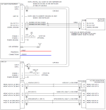
If you add an SL 30, the 430W must become navigator #2. The LNAV2, VOR/ILS 2 configuration inside the 430W selects SDI = 2 for that navigator.

G5 with SL30 and GNS4XXW.png

Steve
 
You never said anything before about having an SL 30 in the installation.....

If you add an SL 30, the 430W must become navigator #2. The LNAV2, VOR/ILS 2 configuration inside the 430W selects SDI = 2 for that navigator.

View attachment 64228

Steve
Thanks - understood - the SL-30 is not in the mix right now. I want to get this working as is first... Testing one installation at a time...
 
Last edited:
Update...:

The 430W is sending data to my AFS-3400s-EE so the issue I have is with the specific wiring from the 430W to my G5 ARINC GAD 29 module.
Based on the additional education provided here, I have configured both the G5 and the AFS-3400 for the 430W to be SDI 2 for consistency.

Now to check my wiring.

Thanks for your help and education!
 
Update - the ARINC A and B for the VOR/ILS signals were swapped at the GAD29.
I have duly chastised the tech that got that wrong - while fixing it.
Looks like it all checks good in the hangar - now to fly it and see how it all comes together.
Great learning forum meanwhile - thanks to all that helped!