jliltd

Well Known Member
I am configuring a G3X Touch with 3 GDU's (first time for 3 screens). I will be using the GDL 52 for ADS-B "in". Can the 52 talk to all 3 screens? The installation manual shows a two-screen set up with each of the two provided RS 232 channels on the GDL 52 talking to each GDU. Will a third display show weather and traffic from the GDL 52 through the CAN Bus (probably not)? If not, since there is not a third RS 232 channel available on the GDL 52 can the RS 232 wires going to GDU #2 (MFD) be spliced into to feed the second MFD (3rd GDU screen)?

Thanks,

Jim
 
I have a 3 screen G3X setup in the -10.

I'd have to look back at my wiring diagram to see how it is all connected; I have a 52R, and traffic / weather / etc is all available in the same format on all 3 screens.
 
I am configuring a G3X Touch with 3 GDU's (first time for 3 screens). I will be using the GDL 52 for ADS-B "in". Can the 52 talk to all 3 screens? The installation manual shows a two-screen set up with each of the two provided RS 232 channels on the GDL 52 talking to each GDU. Will a third display show weather and traffic from the GDL 52 through the CAN Bus (probably not)? If not, since there is not a third RS 232 channel available on the GDL 52 can the RS 232 wires going to GDU #2 (MFD) be spliced into to feed the second MFD (3rd GDU screen)?

Thanks,

Jim

Jim,

Traffic data is shared over the CAN bus, so with just a single GDU 4XX connected to a GDL 52/52R, up to 6 GDU 4XX displays will show traffic.

Weather data is not shared over the CAN bus, so any display showing weather must be connected directly via RS-232 or Bluetooth to the GDL 52/52R.

For a 3 display G3X Touch system using a GDL 52/52R traffic/weather receiver, two displays are normally connected via hardwire RS-232 and the 3rd display (probably PFD2) is connected only via Bluetooth.

Steve
 
Jim-

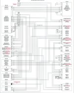
Here is my wiring diagram.
RS-232 to PFD1 and MFD

I will have to re-verify based on what Steve said; I was pretty sure I get weather on the copilot screen (PFD2). It may be that I connected it via Bluetooth in the past and have forgotten that I did so.

Hope this helps.

Thomas
 

Attachments

  • Screen Shot 2020-08-24 at 9.36.13 AM.jpg
    Screen Shot 2020-08-24 at 9.36.13 AM.jpg
    343.9 KB · Views: 389
Thanks, Steve. Does the RS-232 interface between the GDL 52 and GDU 4xxs contain all weather products? I know with the aera portable GPS series only Bluetooth connection provides all weather products because RS-232 is limited somehow (bandwidth?).
 
FIS-B Weather Products

Thanks, Steve. Does the RS-232 interface between the GDL 52 and GDU 4xxs contain all weather products? I know with the aera portable GPS series only Bluetooth connection provides all weather products because RS-232 is limited somehow (bandwidth?).

Good Morning,

We are rounding out the development to include the new FIS-B weather products on the serial datapath, you will see that capability included in a software update in the not-too-distant future.

Thanks,

Justin
 
Good Morning,

We are rounding out the development to include the new FIS-B weather products on the serial datapath, you will see that capability included in a software update in the not-too-distant future.

Thanks,

Justin

Will these updates make it to the 37x series as well?

Larry
 
Jim-

Here is my wiring diagram.
RS-232 to PFD1 and MFD

I will have to re-verify based on what Steve said; I was pretty sure I get weather on the copilot screen (PFD2). It may be that I connected it via Bluetooth in the past and have forgotten that I did so.

Hope this helps.

Thomas

Thomas,

Awesome schematic. It's in the same format I prefer and I do them just like that.

Thanks,

Jim
 
Excellent news, Justin. I have become a real Team X enthusiast.
 
Last edited:
I've documented my system a different way and found it very useful...

Rather than have a wiring diagram with each wire shown, I use a table of inputs and outputs by port, not by individual wire. For example, the GDL52 goes to Serial Port 3 on the PFD and Serial Port 3 on the MFD. In that same table, I have all of the settings for each serial port -- and also for the ARINC 429, no ethernet, etc. I include the information with autopilot settings, and shared circuit breakers, etc. Lastly, I list which serial lines are for backup (e.g., in my plane, PFD to roll servo)

Power, ground and CANbus don't have any settings and don't have flexibility, so I omit them from the table.

I've found that there have been a number of times I wanted to know port connections and settings, but needing to know pins has been very rare by comparison.

And if you do need to know what connects to what, a table is lots quicker and easier than chasing wires in a wiring diagram.

If you like, PM me and I'll send you a copy. Radio shops love it.
 
Thomas,

Awesome schematic. It's in the same format I prefer and I do them just like that.

Thanks,

Jim

Thanks.

Giving credit where credit is due - the diagram is from Tim at Approach Fast Stack - those guys built my wiring harnesses for me based on wiring plans and discussion back and forth over several months. They did an awesome job, and the schematics are invaluable!