J.P. Instruments installation instructions
J.P. Instruments has a similar unit (probably with less electrical noise immunity due to higher impedance) that has
similar installation instructions, look under the Specifications tab. Here's an excerpt:
"Install Overview:
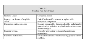
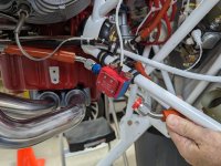
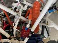
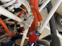
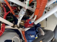
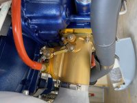
Make sure the transducer is Horizontal with the three wires up. Failure to do this will result in premature failure. Please refer to Report #503 that came with your EDM with Fuel Flow.
Mount in a horizontal position with the wires up, as this ensures that the rotor is in proper orientation to the flow of fuel just as it was calibrated.
Be sure there is no bend in the line closer than 6 inches before or after the transducer. Do not use aluminum fittings when installing the fuel flow transducer.
For carbureted engines, before the carburetor. If the transducer is higher than the carburetor, put an anti-siphon loop in the line that peaks higher than the transducer (see installation manual, but the diagram shows the transducer on its side, rather than the correct position which is with the wires coming off the top).
For injected engines, between the engine fuel pump and the servo regulator. For injected engines with vapor return lines (rare), between the servo regulator and the flow divider (spider).
Mounting the transducer between the electric boost pump and the mechanical pump is not recommended.
Do not hard mount the transducer to the engine. Vibration may damage the internal parts of the transducer or cause erratic readings."
Here's how they describe their unit:
"Here’s how it works in an aircraft; liquid enters through one side and enters the flow chamber. It follows a helical flow path, and exits vertically, thereby venting vapor bubbles that might form during the fuel flow. As the liquid flows, it has a velocity that can be measured and this velocity is directly proportional to flow rate.
Inside the fuel flow transducer, is a miniature neutrally buoyant rotor finely balanced on jeweled bearings. As the fuel flows past the arms of the rotor, it pushes against the arms of the rotor and so, the rotor begins to spin.
Now, on one side of the spinning rotor is an infrared light emitter while on the other side, is an infrared light detector. As the arms of the rotor spin, it interrupts an infrared light and this constant on-off is calculated to arrive at the spin rate and therefore, the fuel flow rate. Ingenious, simple and fool proof.
JPI FF transducers use a more sensitive but rugged version of a typical fuel flow transducer, suitable for a wide range of aircraft use."
Sounds pretty similar to the Red Cube.


")