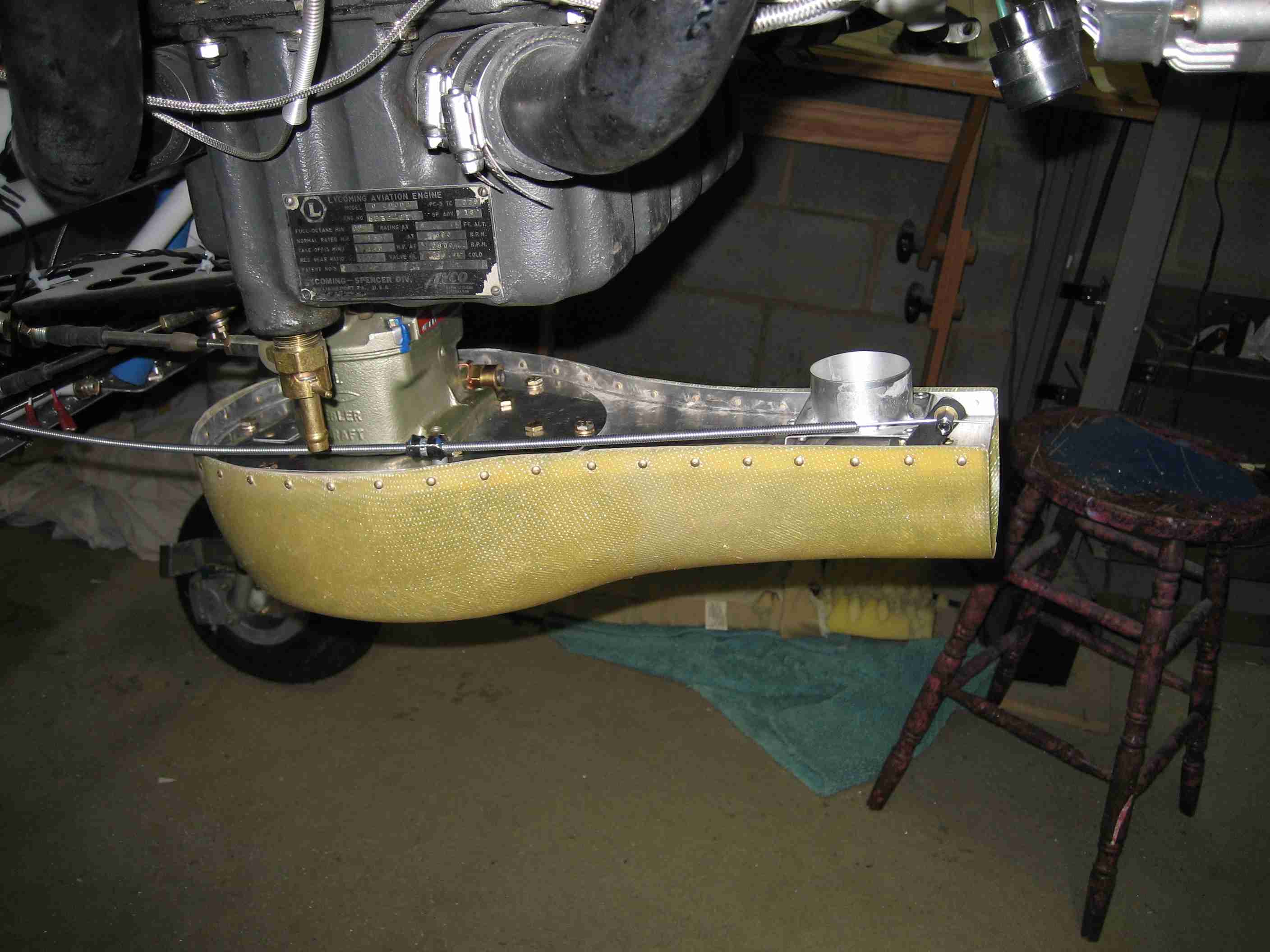
I just bolted my carb to the sump. The bottom of hte carb is open (see pic). Does it stay this way? There are four threaded holes around the big opening, suggesting something eventually gets bolted up to the bottom of the carb...
Also, is there a torque setting for the nuts that hold the carb to the bottom of the sump? Or just hand tighten to compress the gaskets?


Also, is there a torque setting for the nuts that hold the carb to the bottom of the sump? Or just hand tighten to compress the gaskets?