What's new
Van's Air Force

Don't miss anything! Register now for full access to the definitive RV support community.

SafeAir1 Pitot Mast

Arie

Well Known Member
Good day guys
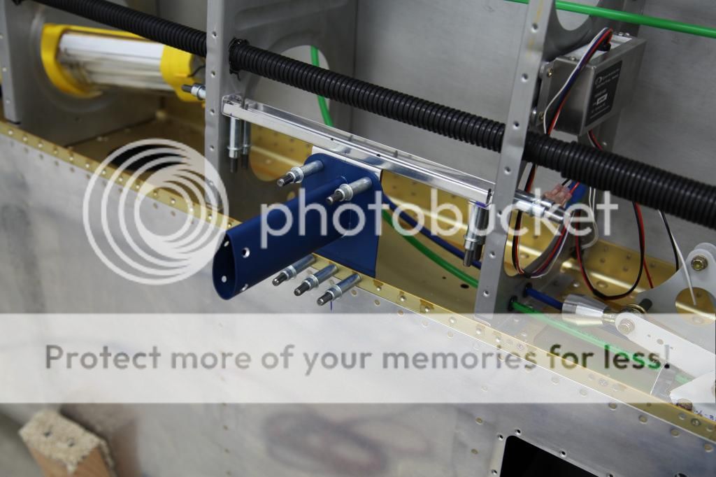
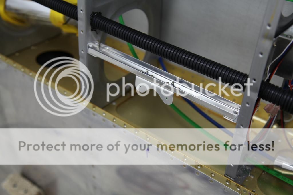
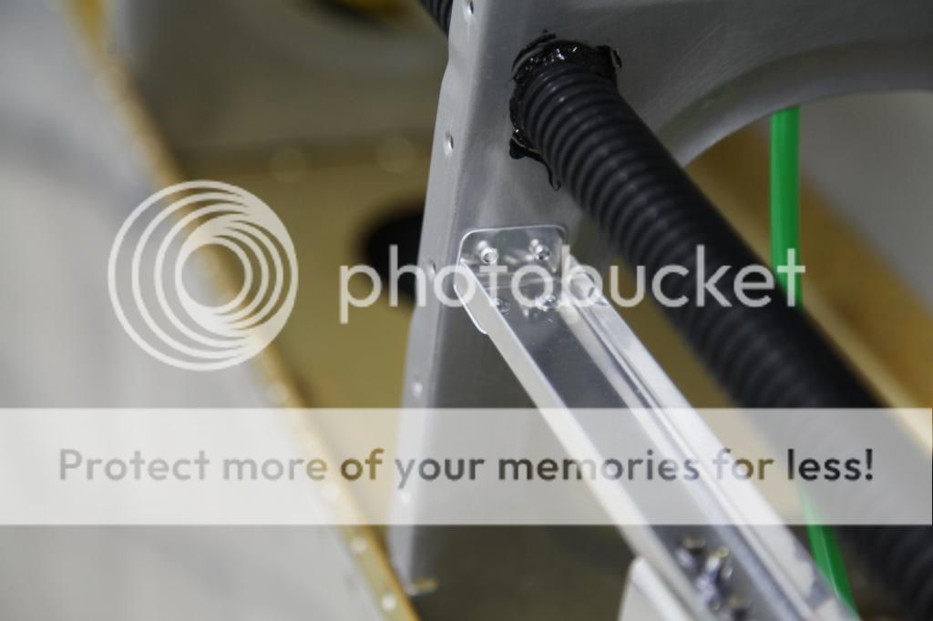
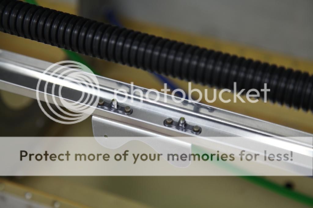
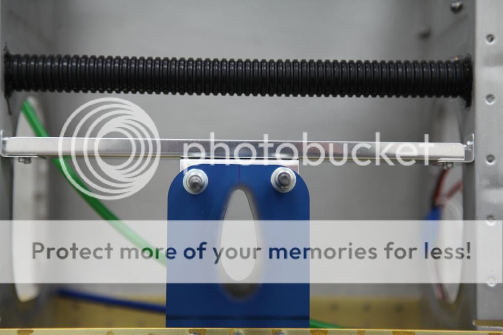
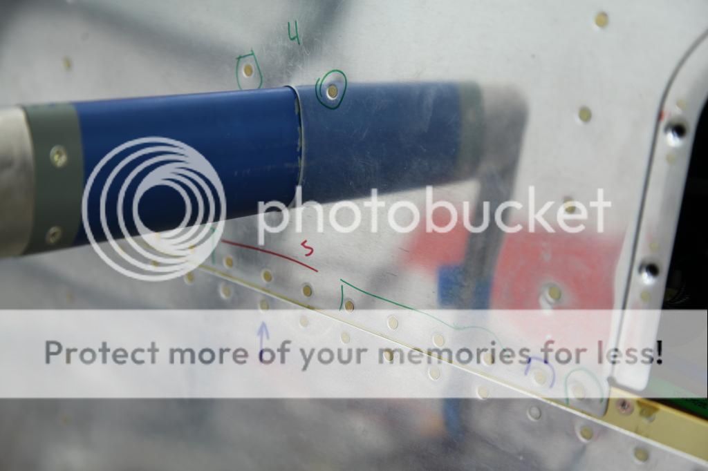
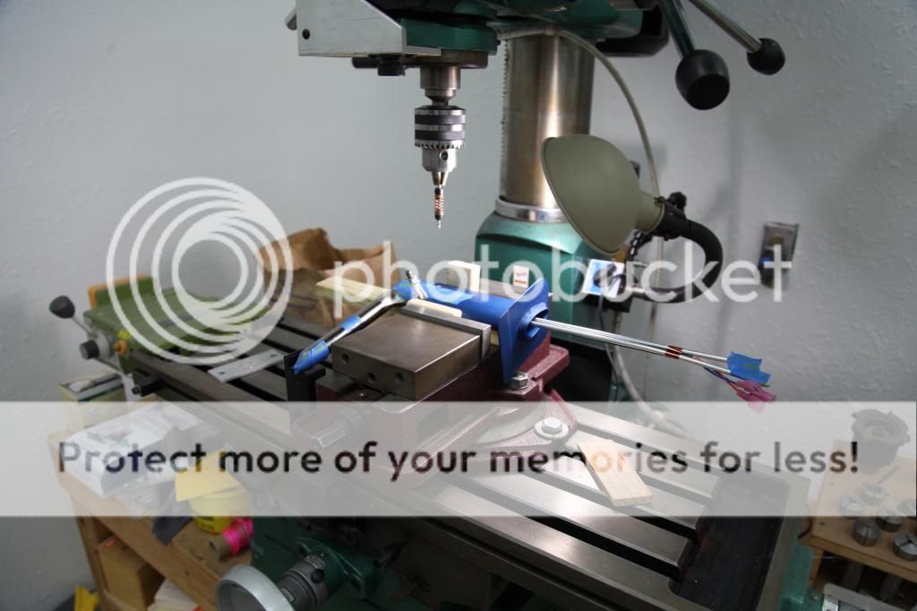
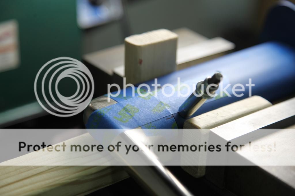
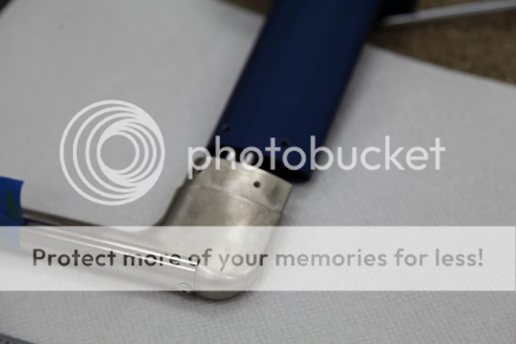
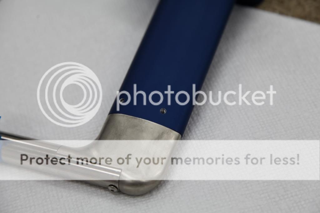
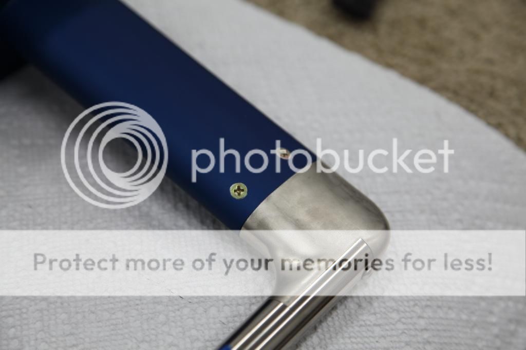
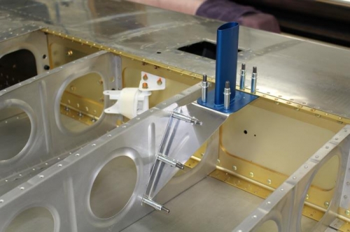
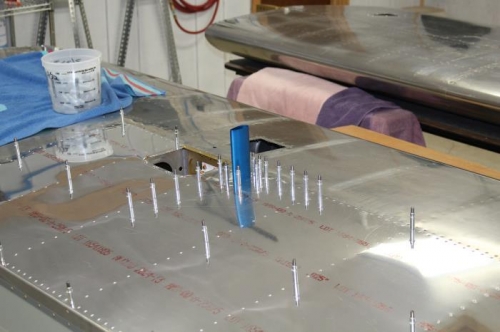
I have fitted my Safe Air1 Pitot mast with the Dynon pitot tube to the bottom of the left wing skin. Just outboard of the aileron bellcrank inspection panel. I followed the instructions from Safe Air for the installation and it came out looking great. I do however have a question regarding the rigidity of the mast where it is riveted to the skin at the back of the pitot mast. The front overlaps onto the spar which is great but at the back I can see some flexing of the skin if I apply a force to it . About 3/16 inch flexing. I think I am going to rivet a light weight stiffener to the skin between the two wing ribs ( like the stiffeners in the bottom of the fuel tank ) aft of the pitot mast mounting plate. This should make the aft side much more rigid. What do you guys think??.
PITOT004.jpg
[/URL][/IMG]
PITOT002.jpg
[/URL][/IMG]
PITOT003.jpg
[/URL][/IMG]
PITOT001.jpg
[/URL][/IMG]
 
Sure

That will work. So will a piece of angle aluminum riveted to the rib, skin and to the mast.

Vic
 
Just finished this same install

I did not measure the flex before riveting, but after the simple install without any extra reinforcement the mast seems pretty rigid after riveting the mast and outboard skin in place. Recall that the pitot plumbing will also provide some strength after final pitot install.
 
I also added a short piece of angle aluminum to the inboard rib, skin and the mast. Everything seems quite solid now.
 
The pix below show how I mounted my SafeAir1 Pitot Mast. I made a small channel (1.00" high X 0.375" wide X 0.025" thick) and a couple of shear clips (0.625" (rib) X 0.75" (channel) X 1.00" high X 0.025" thick) and used some AD-41-ABS blind rivets to hold them together. I made another angle (0.032" thick) to mount the mast to. All of these parts were 2024-T3. I decided to use AD-41-ABS blind rivets since access was pretty tight to try to buck a solid rivet. Although the AD-41-ABS rivets aren't as strong in shear as the AD rivets, the shear clip joint is still 2.25X stronger than the bending of the channel.

I used solid rivets to attach the mast to the skin/spar and mount. If I ever need to remove the mast I can easily drill out the solid rivets. Then I can just unscrew the 0.032" thick mast angle from the inside of the wing and slide the mast upward thru the airfoil shaped hole in the wing skin. You could probably use some #6 flat head screws also if you want. I don't see myself having to pull the mast often enough to warrant that.

You can see the grip lengths I used for the rivets in the last pic (-4 & -5).

This wasn't all that hard to make and install and it greatly increases the strength and stiffness of the pitot tube mast. It also only weighs about 1.05 ounces so you shouldn't get too much of a "heavy wing" because of it!

Aircraft001_zps0521ec99.jpg


Aircraft003_zpsfe49a5b2.jpg


Aircraft005_zpsa7b94bfe.jpg


Aircraft006_zpsa9b68b20.jpg


Aircraft008_zpsf36f8b3d.jpg


Aircraft010_zps88beaeab.jpg
 
Last edited:
Very nice work!

Thanks for this post. I just got a Dynon Pitot, and was looking for a mast. After seeing this, I got the Safe Air mast, and installed it yesterday.

One question for you, where did you get the instructions on how to connect the pitot and mast? Neither the Safe Air, nor the Dynon instructions specified any details.
 
Pitot Mast Installation Instructions

I just looked on this site and on various builder websites on how they installed the pitot tube on the mast. I used my mill/drill since I've got one. You could use a drill press and probably get the same results. I just marked on the mast the "thick" parts of the pitot tube where you want to drill and tap for the #6 screws.

I used some tape to hold everything together while I drilled the first hole. I clecoed that hole and moved on to the next hole and so on. Make sure you don't go too deep and damage the tubes inside the pitot tube. When all the holes were drilled, I deburred and tapped the holes. I then countersunk the mast.

Unfortunately I get to do the drilling and tapping on the pitot tube again since I'm in line to get the new "ice free" pitot tube. It shouldn't be too bad. I'll just slide the new one inside the mast, mark it and then pull it back out to drill and tap the holes. Hopefully everything will line up.


Aircraft001_zps7b3251e7.jpg


Aircraft002_zpsd00aa2fc.jpg


Aircraft004_zps12a4e086.jpg


Aircraft005_zps4b1ab935.jpg


Aircraft010_zps10d6827b.jpg
 
No problem. Glad to have helped. I've learned a lot on this forum. I guess it's time to put some back in!!

Jeff
 
Hello,

I am french and it is a little difficult to adapt me to the imperial measurement system. So, what is the drill size for tapping a #6 screw ? 40 ?

Thank you
Sylvain
 
My solution

Since I used this thread as part of my research for my own pitot mast installation, I thought I'd share my experience today. I purchased the same style aluminum SaveAir/Avery pitot/AOA mast from Aircraft Spruce. Since there are differing opinions on how to install this mast (rear-braced or only skin/spar mounting), I checked with Gus at Van's for a tie-breaker vote. He said that having a rear support might be a good idea... but suggested fabricating a triangular support bracket that would attach to the adjacent wing rib. Once I had the mounting position finalized I cut the mast hole in the skin and used the spar as a template to drill the three front rivet holes and cleco the mast in place. I used card stock to design a template for my rear support bracket, transferred the design to aluminum sheet, cut out the pattern and bent and formed the bracket to shape by hand. I added two additional rivet holes in the plate near the front so there would be a total of seven rivets attaching the mast plate to the skin, dimpled the skin for the flush rivets and had to countersink the holes in the mast plate by hand; the mast obstructed the use of the microstop fixture or drill. I made sure the plate was positioned level to the ribs to simulate skin attachment and match-drilled the bracket and rib. I figured out how assembly would go and test fit the assembly with the bottom skin in place. So far, so good. If I had a way to press reinforcement ridges in the bracket, I'd drill lightening holes... but since I don't, I think I'll leave well enough alone for now. One photo looks like the bracket has a reinforcement ridge... but that's just a reflection of the one in the rib. For more photos and details, see the mykitlog link in my signature below.
FP05042017A0000X.jpg

FP05042017A0000Y.jpg
 
Last edited:
Back
Top