What's new
Van's Air Force

Don't miss anything! Register now for full access to the definitive RV support community.

Electrical issues on my new-to-me RV12

webstarr

Member
EDIT3: We solved it! Problem was a bad connection at the VR. Took forever to find and a minute to fix.

Hi everyone,

I've got a new-to-me 2015 RV12 with a 912ULS that has about pushed me to my breaking point. I won't get into all the mistakes I made as a first-time aircraft buyer, but after many months and thousands of dollars I finally got it running well... and now it's grounded again.

The issue this time is negative amps and no charging on startup. The first time it happened we were getting around -6 amps even during the runup, and "solved" it by cleaning up the the firewall forward connector on the control module behind the Dynon with a little deoxit and dielectric grease.

A few flights later I started getting around -2 to -4 amps after startup, but it would start to charge again once I added higher RPM for the runup.

Then it progressed to where I had to run 4000+ RPM for a considerable length of time to get it to charge.

At this point I decided to bite the bullet and get a new voltage regulator (B&C). The first time we started it up with the new regulator it was charging perfectly! Then the second time... nothing.

Now we're at the point where it won't charge no matter what.

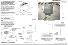
The latest thing we tried was replacing the connector housing and all the connectors to the VR, but that hasn't solved it.

Unfortunately I'm more of a fly it vs. fix it kinda guy, so I may need someone to explain to me like I'm 5. (My buddy is much more knowledgeable about this stuff than I am, so if I need an interpreter I'll pass it along to him.)

Help?

TIA.

EDIT: Forgot to mention we've tested the battery and that does not seem to be the problem. Takes and holds a charge just fine.
EDIT2: From my smarter friend: "The c pin has already been jumped from the b terminal so the fuse should not be the issue"
 
Last edited:
You may have a problem with the permanent magnet generator. Try checking the voltage regulator input voltage to,see if the PMG is putting out any electricity.
 
You may have a problem with the permanent magnet generator. Try checking the voltage regulator input voltage to,see if the PMG is putting out any electricity.

Thank you for the reply.

I must confess I am not familiar with the permanent magnet generator. I tried to educate myself with some Google research but couldn't really find any information on it as it relates to the RV-12. Would you mind giving me a little more insight into what the PMG is, where to find it, etc.?

EDIT: After doing some more research I think I understand the the permanent magnet generator is basically just referring to the alternator/stator? One thing we did note was that the input voltage from the stator to the VR was 1.7V with the engine OFF. Is that normal?
 
Last edited:
More info would be helpful

This problem has come up a lot. Many times it is a problem with the yellow VR excitation wire.

Can you post a picture of your voltage regulator and how it is wired?
How is your voltage regulator wired? Does the wiring look like this with particular regards to the short yellow jumper wire from pin 4 to pin 6 on the B&C regulator?
 

Attachments

  • Screen Shot 2023-06-01 at 7.07.24 AM.png
    Screen Shot 2023-06-01 at 7.07.24 AM.png
    944.1 KB · Views: 154
This problem has come up a lot. Many times it is a problem with the yellow VR excitation wire.

Can you post a picture of your voltage regulator and how it is wired?
How is your voltage regulator wired? Does the wiring look like this with particular regards to the short yellow jumper wire from pin 4 to pin 6 on the B&C regulator?

Thank you for your response. I will take a picture next time I'm at the hangar and post it.

I can say, however, that the yellow wire is definitely jumped as shown in the picture.
 
It is a bad idea to put a jumper from the "C" terminal to the "B" terminal
because if there is smoke in the cockpit from an electrical problem, shutting
off the master switch will not shut off the power. The charging system will
keep working until the engine RPM slows down or stops.
-
The permanent magnet generator is unlikely to fail because it has no moving
parts other than the magnets that are attached to the flywheel. When it
does fail, the most likely cause is a spade terminal on a heavy yellow wire
that connects to the voltage regulator.
-
The most likely cause of low voltage is the voltage regulator. I recommend
replacing it with a John Deere regulator. Search eBay for AM101406 or
MIA881279. They cost about $20. The small yellow wire connects to the
IGW terminal.
-
No matter what voltage regulator you buy, it will fail if not installed properly.
Heat conductive paste should be used between the metal part of the
regulator and the mounting surface. A blast tube should blow air onto the
regulator fins. And the plastic terminal housing should be discarded. Each
wire spade terminal should be connected individually so that you can tell how
much force is required to connect it. Terminals that slide on easily will not make
good contact and will make heat that will damage terminals or the voltage regulator.

Thank you for the reply.

I am aware of the arguments for and against jumping the wires. I am open to exploring alternative methods of wiring the VR in the future once I get the thing working.

I did just replace the VR with the one from B&C. We also replaced all the connectors and the connector housing to make sure everything was snug and proper. We positioned a cooling hose to blow right onto it and ditched the cover.

What was weird was that it worked perfectly when we started it up the first time after installing the new VR, but it hasn't worked since...
 
Have you confirmed that the regulator has a good ground, with a ring terminal on the regulator case and a 12 AWG wire going directly to the battery negative terminal or the engine block?

Remember that the regulator really has seven connections:
- AC input (two pins, to the AC generator in the engine)
- Miscellany (two pins, the warning light and the control pin which you've already checked)
- DC output (two pins for power, and the regulator case for ground). A bad ground on the regulator case will break the circuit just like disconnecting the DC output.

Thank you for the reply. The ground appears to be perfect. We're working through double-checking all the wiring and connections right now but so far no smoking gun...
 
As Joe says in Post #10 above.... For $20 buy a John Deere VR to try. I replaced my Ducati VR early-on and have been running the JD since. I keep a spare in the baggage compartment.

Joe knows electrical....
 
As Joe says in Post #10 above.... For $20 buy a John Deere VR to try. I replaced my Ducati VR early-on and have been running the JD since. I keep a spare in the baggage compartment.

Joe knows electrical....

Thank you for the reply.

I'll order the John Deere VR right away and give it a shot.

Wish I had consulted you guys before I bought the B&C. Yet another lesson learned...
 
Most generators and alternators use a field winding with electricity running through it to create a magnetic field on the generator rotor, and the output voltage is controlled by the voltage regulator that changes current in the field winding to maintain a desired bus voltage. PMG use a permanent magnet instead of a field winding and output voltage varies with RPM. The voltage regulator takes the output voltage and passes what is needed to maintain bus voltage.

Problems with the PMG could be a failed armature coil (the armature is where the output voltage is created by the spinning field), but as Joe said it is much more likely that the fault is a broken wire or terminal connection interrupting the continuity in the generator output path to the regulator.
 
Wiring harness issue

I had the same issue that Dale had with the wiring harness that connected the output of the voltage regulator to the power distribution on the instrument panel. Namely, no continuity between the two wires that connect to the voltage regulator and continuity to the single wire that varied when crimp was flexed.

And the crimp on the terminal of the single wire end was improperly crimped. The crimp that was supposed to be on the stripped conductor was on the insulation.

Brett H
Columbus, IN
 
It is a bad idea to put a jumper from the "C" terminal to the "B" terminal
because if there is smoke in the cockpit from an electrical problem, shutting
off the master switch will not shut off the power. The charging system will
keep working until the engine RPM slows down or stops.

What is the purpose of jumping B & C together?
 
Same thing happened on my first engine run

I had the same issue that Dale had with the wiring harness that connected the output of the voltage regulator to the power distribution on the instrument panel. Namely, no continuity between the two wires that connect to the voltage regulator and continuity to the single wire that varied when crimp was flexed.

And the crimp on the terminal of the single wire end was improperly crimped. The crimp that was supposed to be on the stripped conductor was on the insulation.

Brett H
Columbus, IN

I had the same issue as Dale and Brett, a wrongly crimpled cable on the output of the VR. On the first engine start the battery didnt show any charge. Don't rely on any of the supplied connections and crimps, mine was hard to identify because continuity only failed sporadically. Try moving and twisting the cables while you check for continuity.

My two cents, hope it helps.
 
Back
Top