Read through all the engine "how to's" here on VAF to help you prep - such as this recent post by Draker, where I had the pleasure to help the install.
https://vansairforce.net/community/showpost.php?p=1488835&postcount=4
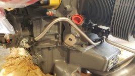
Don't remove the mags, etc ... all the pre-installed installed items can stay in place and be sure to add the hard to install items, like the oil pressure fitting prior to install.
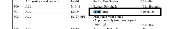
For torques and things, post a copy of the relevant pages of the Lycoming SSP-1776 (
https://www.lycoming.com/special-service-publication-no-1776-5) doc that gives specs for the torques of all items on the engine.
Like primer, you mileage may vary but I've used the technique, below, twice with excellent success.
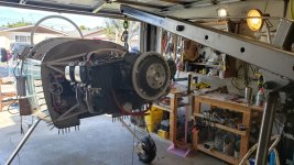
Hanging the engine
August 27, 2015; archived from"http://myrv8.com/2015/08/hanging-the-engine/" which does not seem active any more.
Short version is this: Their advice was to forget the procedure I’d been trying. Instead, they said, mount the two bottom bolts and isolators first. Only after that, use the lift to manipulate the engine and get the top ones in with the bolts lined up, and the isolators will be offset to the outside of the “cups” in the engine mount. Get a good heavy rubber mallet or a piece of 2x4 and heavier hammer, and start tapping the mounts to get them to slide laterally into the cups on the mount. Then move the engine relative to the air frame to get things to move into place and together, and get the bolts in. “You’ll never get it the way you’ve been trying,” I was told. Use the bottom-first method and I’d be done in a handful of minutes.
1. Prepare all the hardware. Make sure the (slightly) longer bolts will be used on the bottom mounts. The shorter ones go on top.
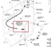
2. Note that the mount biscuits are of two types – one is a little less think and is harder, and the other is slightly thicker and a softer rubber. They look different. Refer to the drawing. Also, refer to the drawings, and then do so again. Don’t get this wrong. The engine’s weight load goes on the harder halves, meaning at the top mount points they are closest to the firewall/on the back side of the mount points, and on the bottom they are located on the front side of the mount, between the mount and the engine block. The side that gets squished by the weight when the engine is hanging on the mount in a positive-g, upright position is where the thinner/harder ones go.
3. Refer to the drawings. Know them well.
4. There are metal spacers tubes in the kit which you will use. Don’t forget them like I did with one. They slide onto the both in the gap between the mount halves and prevent the rubber mounts from squeezing too close together, and prevent them from bottoming out.
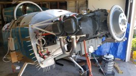
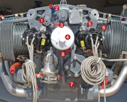
5. Hang your engine on the hoist. Remove any hoses or items that might get in the way.
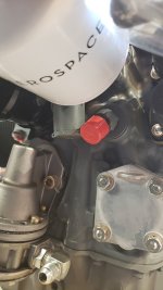
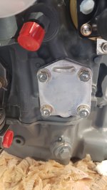
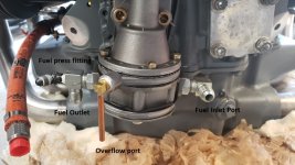
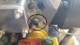
6. Make sure you have inserted the oil pressure line’s restrictor AN fitting at the right top rear of the engine. It faces outboard and the 45-degree fitting needs to be inserted before you mount the engine or else you won’t be able to get it in there. Some engines (mine included) have a second port that faces directly aft, and you can put a straight restrictor fitting in there if you like. But check and make sure. Best to install it permanently before you mount the engine.
7. Move the engine into place on the hoist. Insert the lower mount rubber biscuits and the thick washers used on the lower mount points between the engine mount and the engine block first (these are the thinner/hard ones). Don’t forget those two washers that go on the bottom, and be sure to put the spacer sleeves on the bolts when you insert the bolts, the larger washers and the other half of the shock mounts on the aft side of the engine mount.
8. In my case, it was pretty easy to get the bottom mounts in place. Don’t worry about getting the rubber biscuits centered in the cups on the engine mount. Just get the bolts through them and into the holes in the engine. If they line up, great. If not, use a rubber mallet or a piece of 2x4 or similar block of wood with a hammer to tap the mounts in to place. Start with the ones on the engine side of the metal engine mount, then the ones on the aft side.
9. Tighten both bolts and nuts until they tighten down on the spacers.
10. Next, use the hoist to move the engine up and about level. Try to insert the bolts through the large washers/rubber pieces/spacers and the holes in the engine block. The last part will likely be difficult and there’s a very good chance that when you get the bolts just barely inserted in the engine, the rubber pieces will sit quite a bit outboard and not in the cups. Do your best to get things lined up and as pushed together as you can along the bolt axis.
11. Use the lift to raise and lower the engine a little bit at a time. Try to get things to further come together. In my case, I lifted the engine until the nose gear on the 8A was several inches off the ground, and all of a sudden things started to fit better. I was able to slide the rubber biscuits together more and the bolt went in just a little further. Not all the way, but enough to lower the whole things somewhat and have things stay in place.
12. Once back on the nose gear (and with the wheel barely touching the ground) I again took the 2x4 section and hammer and started working the rubber pieces into the centerline, tapping until they popped into place in the engine mount cups. Them some more raising and lowering to get things further aligned, and finally dropped the hole thing onto the gear, keeping just some weight on the hoist chain.
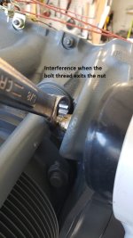
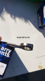
13. At this point I was able to get a socket wrench out and turn the bolt, which immediately threaded its way through the engine case holes and out the other side. Then came washers and nuts, and all was done.


 Who ya gonna trust?