What's new
Van's Air Force

Don't miss anything! Register now for full access to the definitive RV support community.

G3X: Measuring voltage via GP pins

gfb

Well Known Member
For the sake of completeness, I'm measuring voltage/current at the following spots:
- Main battery (GP 4)
- TCW battery (GP 3)
- Main alternator (Volt 1, Shunt 1)
- SD8 alternator (Volt 2, Shunt 2)

I assume the GP3/4 are fine for voltage, but can I also use them for additional shunts or hall effect sensors?
 
Is this for a GEA24 or GSU73? If it's the GEA24, I just went through this same process of identifying what connects where. You can use the POS/GP inputs for any voltage measurement referenced from ground, which will work fine for your battery voltages etc. However, I don't believe it will work for shunts, as those need to measure a voltage *differential* on both sides of the shunt. The GEA24 does have two shunt inputs though (I think the GSU73 does too, right?), which you can use to sense current as you wish.

In my case, I wanted a third current measurement (Bus 1, Bus 2, and E-bus), so you can't use a shunt for the third device, but you can use a Hall Effect current sensor, which outputs a voltage reference to ground and can connect to any POS/GP input. Garmin recommends the Amploc KEY100 series in the install manual, however I went with an ACS758 (see link here) and built it into a custom-made E-bus controller/isolation board. I'd be happy to share more details on what I did, but it may be beyond the scope of your original question.

Hope this helps!
 
Thanks for the response.

Yes, I just ordered an Amploc KEY100 for my bus current sense. Can you tell me more about your bus isolation/controller?
 
Sounds like that will work for you!

I'm running a dual battery/dual alternator setup in which both systems are completely isolated from each other during normal operation (except when cranking the engine), with a small third backup battery to handle power interrupts and/or run essential equipment should both buses somehow fail. I had considered TCW's products as well as a few others, but none of them did exactly what I wanted, so I decided to DIY. It's been a long road and we're nowhere near done yet haha.

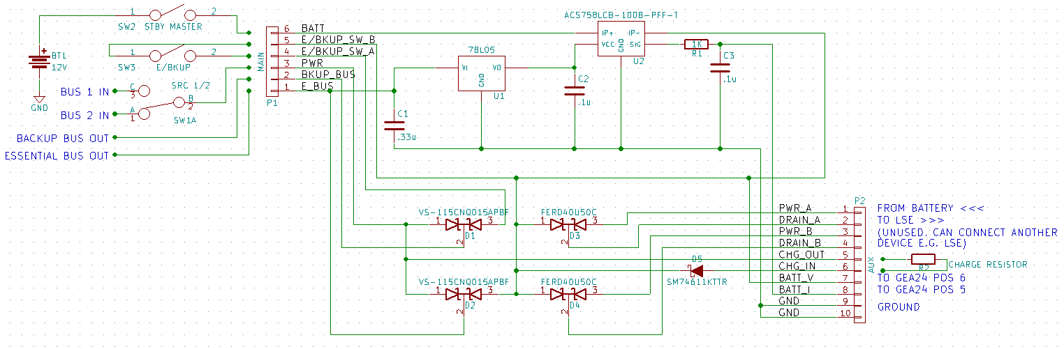
I designed a circuit that would take a power input from either Bus 1 or 2 (selectable via a toggle switch) and feed it through a high-current Schottky diode array (VS-115CNQ015APBF) out to the E-Bus. The other side of the diode array is powered by the standby battery, which will automatically source the E-Bus if the primary power source fails.

The board actually has three blocks similar to described above:
1. A "backup" bus that powers my entire "Avionics 2" bus. This can be switched off via an external switch to prevent excessive draw, but when turned on will be able to power almost all of my avionics including all displays etc during engine cranking.
2. An "essential" bus that powers a few essential components and a standby flap/trim circuit
3. Using a smaller-rated FERD40U50C diode array, this backs up one of my LSE ignitions, which has its power sourced separately (they connect straight to the battery).

The Hall Effect current sensor I mentioned earlier (ACS758LCB-100B-PFF-T) is connected inline with the battery input, and measures bidirectionally so I can see if the battery is charging or discharging. I can even set up an alert on the G3X to tell me if the standby battery is draining, so I will be aware if something isn't working correctly.

Since the current sensor needs 5V DC to operate, I also needed to include a small power supply on the board that uses a simple 78L05 linear voltage regulator, with other supporting circuitry.

In use, there are three toggle switches associated with this system, (1) a stby battery master switch, (2) an e-bus source to select Bus 1/2, (3) Backup/Essential mode only (this disconnects the Backup bus from the stby battery).

I've got all this laid out on a PCB and sent the design to OSHPark to fabricate a board for me. I expect to receive it sometime this week or next, and can keep you posted on progress!
 
Sounds pretty interesting, please keep us posted. Is the circuit diagram available for us to take a look at?
 
Here's a photo of the diagram. I added in a few notes and external components to give the idea of how it all goes together.

Some improvements could be to make a better charging circuit, right now it just accomplishes this through a 2.5-ohm 50W resistor and ultra-low drop schottky diode, but that may change as necessary (it's very inefficient and charging currents would be very low near full charge, but that is probably ok)

You'll also see that there are four blocks instead of the three I mentioned earlier. I had initially wanted to run both LSE's through this, but am now thinking just one in order to prevent any kind of common-mode failure. The fourth block (PWR/DRAIN B) is marked unused.

Comments welcome! I'm no pro at this (I'm much more of a software than a hardware guy) but I know just enough to experiment and get myself into trouble ;)

KunTlAuL7gD_Gx35Ow8QIKQMD2Mm11OwmvIusQM6hE2aZfEX-1gHBi9hnDku7HqbAjtZDLpnkdGXYdD6WlvpH6CyORt9RNMwJ8iR72jeJOOAS3SHumCtBtlqzSIqsB2skmVYAKBMG23iqj9IotOgF0CWcguLFpnaGbzXC5lR4blH1KbH0OOPkz9JqHPx3mjotYJC-7McNhYpNoNlrBtHkMZwb1Hxgc1T9o6OniDI-y44iEG1FyfgPReqNTx3jNR5VPGaTngLVhpT55AZQ0ziv0tEylNeiTfidnz2V3XMTpD5YtU-IXxaO5ib_QeOGyf02yuKFHNe4zDH99udsO7MxZodU0JiN9Hw9GisKKBdfkHqVbeApAI4Eqxq5J1b2G9tuz-Xoufc4gclxEhzFaYP0R4cfA_PMQ8wJrxJU0GQrurZYzFavuUlQRJK0MzJLBUV7cQKjX5IKRvg5h0vDeku-2h-9SbqVEeGw-_bfMeCqsK6fndf2gQOxp5Im9qKyfSYpZz0kg-Nm4WGx2pcsv_kLCtSc_d5nzhTsyfZXbmwaECRLfU09sj9UlS9qVo94cD7NhX-9tlyDUe6nod76H6TQNraeGvozRfQjTpN4MnHFa55VUwlWv8v_J7grFf_aYszk3bgWJXjKIFPOVnvZJmM1lvl_PgilarmY1DmM_lxng=w1524-h501-no


(A quick disclaimer, this is still in prototype phase and should not be used in-flight without rigorous testing... I will not be held responsible if this does not work as expected!!)
 
Last edited:
Back
Top