What's new
Van's Air Force

Don't miss anything! Register now for full access to the definitive RV support community.

Fuel Tank Sender Pics

cderk

Well Known Member
Does anyone have any photos of the fuel tank senders installed? I'm having a heck of a time figure out how to get these set up properly. The vent line is in the way, the stiffeners are in the way - nothing seems to work properly.

Here are some photos of what I have. Seems like I'm getting between 40 and 240 ohms - full to empty.

Thanks!
Charlie
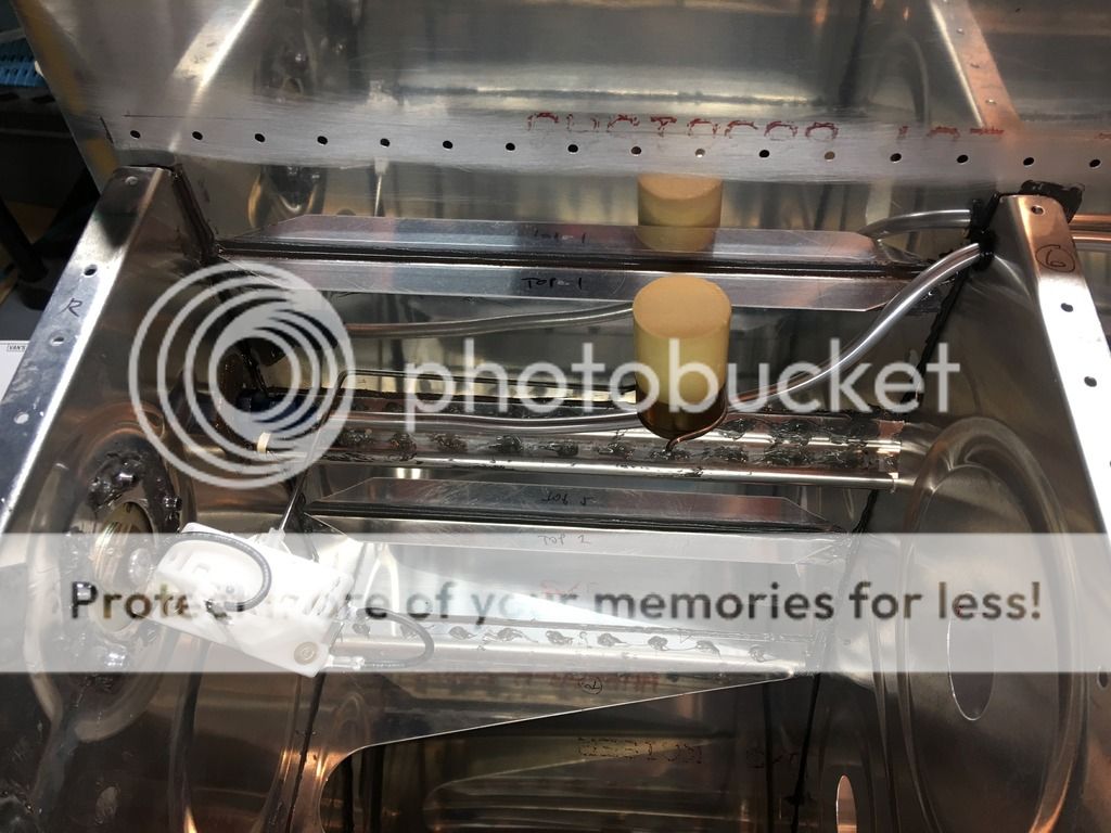


Hi Charlie, feel free to check out my blog on this, some pics you may find helpful are here:

Both tanks here, but we redid the L tank in a later post:
http://mikeandsarahrv10.blogspot.com/2015/04/fuel-tanks_29.html

The later post with the L tank again:
http://mikeandsarahrv10.blogspot.com/2015/05/fuel-tanks-proseal-bottle-6.html

I remember that it took a bit of finagling but we finally were able to get both R and L senders to move freely around obstacles and go through their full swing on the potentiometer. Feel free to reach out if you have any further questions, and best of luck! -Mike


EDIT: Is there a reason your vent line isn't routed through the hole circled here?

qs1aL3S4v3cOr9FXW_zCpyg1R_Y3an4TzO8LpnMHN00XY74ZwAZLjPnQhUaU63P2YlnWIRzceAd4mYI5jHKtOIRf_MEnHvkO7R98tOjPcB0P28hIVUDFvWlJR-4BvBpGZtB28bvH9rKvUGtmq6FKwFkvm3V24ifxGVyXo8Lis8Fb9YHzax98U48sOl-7D8cRvuu2nJc55_10-C37VlEuga2b3OVC5nudpkYOyhM8U-U-xZa2Y9Q6Z8aGVeaNmRmEoGNrjIk8CjGwrialGGe39rbMvclPiGL_UcHNDmgMM523cLPJcVGzJzxLMgvNODqAhFVVB1CnDS6GK_2u16cpS_L2UdGoGcTR4GtgPWsSaRXN0Ih_skrfOEVRfiqWMpUyEkIL5OPYjQXWnZkK-py0l61RXtiTjxfGmO9GL6qfL1acPCpTT1AU9Cnx4id-Oy4CBfivJuNPYQBZ0VgTHu9ZnmzyWh_vJtjsdCM0sfkP2WVBEzECBgYzZ5egePa61OUAwmhbK5u4s_wvW9z0fXL3FR9fgH8ahZENtKEbtXFKnYrvtEXPUR7d8ixJwTyfXu1VCR9V_fjw39O2GBshf8mH3jlLaNBiI8Zi3-G1RQ23o1gK3P6xPz0V=w1024-h768-no
 
Last edited:
I'm sure this is just me not seeing the photo well, but is the float moving fore-aft instead of up-down?
 
Thanks for the photos mike... looks like my first mistake is that i ran the vent line in the aft-most hole, which does not look like what you did. so that will eliminate some of the bends in the line, which may make it easier for me. I also see that you put a few extra bends in the wire holding the float, which probably helped put the float in a better position to clear obstacles.

Guess I have a little more playing around to do - the tanks have definitely been the most time consuming/frustrating part so far...

Thanks again,
Charlie
 
I just realized in the plans (if you look at 18-6 Fig 2) your vent lines look correct, and mine do not. I'm guessing it's not a huge problem either way, as long as it is routed correctly by the fuel cap, but just wanted to point this out.
 
Last edited:
I just realized in the plans (if you look at 18-6 Fig 2) your vent lines look correct, and mine do not. I'm guessing it's not a huge problem either way, as long as it is routed correctly by the fuel cap, but just wanted to point this out.

I've looked at it a few times now. Originally, I thought my method was correct, but then after I looked at your photos, I went back to the diagram and I can argue that yours looks correct. I ripped out the vent and moved it down to the same holes you used and that solved 99% of my problems. I don't know what the other holes are for... guess I would have to look ahead to see if any wires are routed there, but I kinda doubt it. Doesn't seem like either hole would make much of a difference. Your method definitely keeps the tubing in a much straighter line.

Thanks again
 
Back
Top