What's new
Van's Air Force

Don't miss anything! Register now for full access to the definitive RV support community.

75% power?

HP for 160 kts may be..

My "triangle tool" is just a spreadsheet that uses accepted math and is not necessarily going to reflect reality. However, I have found that it's pretty close most of the time.

I set it up with some changes from my plane to make it go 174 kts on 135 HP at 8000' DA and then asked it for the HP at 160 kts = 184.125 mph. It says you need 108.67 HP. This is using an assumed prop efficiency of 82% in both cases. That could be high, but it did not change in this "test". It is the number that Craig Catto suggested for this kind of thing. The spreadsheet is using both induced and parasite drag and is being forced into a L/D that is close to what you are actually getting, but certainly not exactly right. I am replying only because the result is much different than you were expecting.

Not sure the reasoning here is correct.

If it is demonstrated that it takes 135HP to achieve 174 knots, is it reasonable to assume it will take 124 HP to achieve 160 knots?
 
If it is 105 HP, the BSFC would be .49.

How so your math Ross?

If 174/135=160/x, x=124 not 105.

The simplest physics is if you can ignore induced drag, compared to parasitic drag. Pretty good approximation at cruise speed, bad at low speeds.
Parasitic drag is proportional to velocity squared.
Drag has to be balanced by thrust. If prop efficiency doesn't change, then thrust is proportional to Power divided by velocity.
Put it all together, power required is proportional to velocity cubed, not linear at all as you have assumed.
These approximations are pretty close to Heavans more involved calculations.
 
If it is 105 HP, the BSFC would be .49.

How so your math Ross?

If 174/135=160/x, x=124 not 105.

As I said previously, if we don't take induced drag into account, power required varies as the cube of the speed, in other words 8 X the HP to double your speed. If your RV requires 135hp to go 174 knots at 8000 feet DA, it would require 1080hp to go 348 knots!
 
Last edited:
Good information, I learned something today.

My calculations for BSFC may be just as skewered, I am no trained engineer or test pilot and for sure it is showing. It has however been a reason to fly everyday this week and I've enjoyed it. :)

Thanks to all for your input. This place is loaded with some very smart pilots.

Test flying can be informative and fun- and sometimes tedious or scary. :)
 
In deed Ross.

I recall your crash landing in the 6 a few years back when the electric system failed with a Subby engine. :)

Yup, was during a test flight to correlate EGT vs. AFR. Lesson learned to use actual Denso alternators instead of a lower quality copy, have a backup battery installed just in case and include an aural warning low voltage system instead of just warning lights.

I learned a number of other lessons about recognizing charging system failure and deadstick techniques off airport too... A painful but invaluable way to learn important lessons which will stick with me for the rest of my flying days.
 
Degrees ROP at full rich?

Not wanting to cause too much of a thread drift.... but... does anyone know approximately how may degrees ROP an O-360 will run full rich? I have an EFI system and can adjust the range of mixture adjustment. I'm seeing around a 275 degree decrease in EGT from peak to full rich. Does this sound about right? I don't remember the the MP, but I was not WOT and at around 4000' on a hot (72 OAT at that altitude) day- if that matters. My fuel flow seems fine at take off and full rich(approx 17 gal/hr). I'm asking because I only have so much range on the mixture adjustment and the leanest I can get is about 35 degrees lean of peak. If the 275 on the rich side is too much, I could off set the entire fuel map to the lean side and be able to run even leaner than 35 degrees. It is still running great at 35 degrees LOP (no sign of stumble) and I'd like to see if it would be more efficient at an even leaner setting. My GAMI spread is less than .3 gal/hour. Additionally, I could increase the fuel flow on the fuel map at high mp settings to maintain the 17 gal/hr for take off. Anyone know???
 
Not wanting to cause too much of a thread drift.... but... does anyone know approximately how may degrees ROP an O-360 will run full rich? I have an EFI system and can adjust the range of mixture adjustment. I'm seeing around a 275 degree decrease in EGT from peak to full rich. Does this sound about right? I don't remember the the MP, but I was not WOT and at around 4000' on a hot (72 OAT at that altitude) day- if that matters. My fuel flow seems fine at take off and full rich(approx 17 gal/hr). I'm asking because I only have so much range on the mixture adjustment and the leanest I can get is about 35 degrees lean of peak. If the 275 on the rich side is too much, I could off set the entire fuel map to the lean side and be able to run even leaner than 35 degrees. It is still running great at 35 degrees LOP (no sign of stumble) and I'd like to see if it would be more efficient at an even leaner setting. My GAMI spread is less than .3 gal/hour. Additionally, I could increase the fuel flow on the fuel map at high mp settings to maintain the 17 gal/hr for take off. Anyone know???

EFI with Lycoming is Greek to me.....but if you set A/F ration to 11:1 for take off and made that full rich you could not go wrong.

Whether or not there would be enough adjustment to go leaner than 35 LOP, I don't know. Seems like there ought to be.

EGT range from rich to peak has no relevance, the numbers are only useful when going LOP or ROP for performance. The critical setting is for take off, it must be rich enough to protect the engine and it is my understanding 11:1 will do it. You never need more fuel than that in flight.
 
EGT range from rich to peak has no relevance, the numbers are only useful when going LOP or ROP for performance. . .
This is a very important concept to pay attention to!

Whether one has an EGT instrument read out 35 LOP or 10 LOP or 50 LOP or whatever, is really only relevant during the act of transitioning to LOP operations. After that action occurs you need to concentrate your attention more to your CHT readings and fuel flow readings. These data pieces will then be the more important things to monitor while one is operating LOP. The reason one needs to monitor EGT while in the act of transition from ROP to LOP operations is because EGTs are more sensitive to mixture changes. Therefore they will be the first indication that something is going awry.

When one has achieved LOP operations however, those EGT numbers are not as critical to monitor as CHT. After achieving LOP monitor closely CHTs. At that point EGTs will stabilize somewhere and pretty much each cylinder's temperature should be in some specific range relative to the other cylinders. It is here that one should turn to monitoring the CHT of each cylinder along with the relationship of CHTs of each cylinder in comparison with the others. The CHT spread is valuable information as is the actual temperature of each cylinder (they should be showing much cooler temps than when you were climbing or during your leaning process). As long as one is not cooking the exhaust valves above 1450 or hotter, the EGT numbers "are what they are".

As an example of operation with my 9A engine (IO340, 1 slick mag, 1 Lightspeed Plasma III EI, Catto 68x74, forward facing cold air induction), In cruise configuration I routinely run power settings around 2300-2500 RPM, MP is very dependent upon altitude but in the 4K-10K MSL range it will be somewhere in the 22-25 inches range, CHTs in the 290-320 range, oil temp 175-185 F, Fuel Flow 7.0-7.5 gph, and EGTs anywhere from PEAK to 25 or 35 LOP (which usually equates to EGTs somewhere in the 1370-1450 F range). The CHT spread is typically anywhere from 0-15 F from the coolest to the hottest cylinder (most of the time 3 of 4 cylinders will be within 1-5 F of each other and perhaps the hottest one 10 or so out from the others), and EGT spread is usually 20-30 F coolest to hottest. Depending on altitude, wind, etc. this will equate to around 165-175 mph TAS cruise speed.
 
Not wanting to cause too much of a thread drift.... but... does anyone know approximately how may degrees ROP an O-360 will run full rich? I have an EFI system and can adjust the range of mixture adjustment. I'm seeing around a 275 degree decrease in EGT from peak to full rich. Does this sound about right? I don't remember the the MP, but I was not WOT and at around 4000' on a hot (72 OAT at that altitude) day- if that matters. My fuel flow seems fine at take off and full rich(approx 17 gal/hr). I'm asking because I only have so much range on the mixture adjustment and the leanest I can get is about 35 degrees lean of peak. If the 275 on the rich side is too much, I could off set the entire fuel map to the lean side and be able to run even leaner than 35 degrees. It is still running great at 35 degrees LOP (no sign of stumble) and I'd like to see if it would be more efficient at an even leaner setting. My GAMI spread is less than .3 gal/hour. Additionally, I could increase the fuel flow on the fuel map at high mp settings to maintain the 17 gal/hr for take off. Anyone know???

Yes, you should probably re-map towards the lean side. 275 ROP is very rich (theoretically around 9.5 AFR which should be near the rich misfire range and there is no reason to operate there as power is reduced noticeably and fuel flow is very high. As David said, no reason to run richer than about 11.0 AFR, call that around 150F ROP.
 
Thx Ross!

I was hoping you would chime in! I actually have another question I think you might be able to help with as well, but that would be a huge thread drift. Look for a "mag drop" question with electronic ignition.

GEM
 
Recommend you declare victory

I've been following this post with interest. I see two major things wrong with the methodology and goal.

First is the idea of determining 75% power is impossible to know until DanH comes up with a torque meter (that we can all borrow). Further we don't have a good grasp on propeller efficiency. I think I recall from one of my old flight test manuals the military used a figure of 0.78 as it was too difficult or impossible determine the actual number.

Second is your instrumentation. Did you use a sensitive altimeter, a sensitive air speed indicator. These are flight test calibrated instruments and expensive. Further, was your pitot system on an extended boom out in the free stream mounted on a swivel head? You were within 1% of Vans numbers but I'll bet you error bars are greater than 5%.

I would declare victory.

Thank you Don. :)
 
EGT range from rich to peak has no relevance, the numbers are only useful when going LOP or ROP for performance.

The standard test for determining if full rich is in fact rich enough is to climb to 24", set 2400 RPM, allow time to stabilize with mixture full rich, record all EGTs, then lean to peak, recording peak value for each EGT in turn. The difference between full rich and peak should 175-225F. Max power centers about 125 ROP, so the 175 end at full rich is preferred if you want the power you paid for.

The above is an upper limit power setting for this test. Data says some angle valve motors will exhibit significant detonation intensity at this setting IF cylinder heat, oil, and intake air temperatures are at their limits. Should be OK with at normal temps (like 375 CHT, 185 oil, and 60F intake), so let it cool off after climb.

As David said, no reason to run richer than about 11.0 AFR, call that around 150F ROP.

Call it around 200 ROP.

First is the idea of determining 75% power is impossible to know until DanH comes up with a torque meter (that we can all borrow).

You might be amused to know that the idea of a community torque meter was heavily discussed on the old AirSoob BB back in the 90's. The goal was a propshaft extension with a wheatstone bridge strain gauge set, and the necessary electronics to get the signal off the rotating shaft. It would provide torsional vibration information at any RPM, and mean torque for computing HP.

Later I actually did build such a propshaft as part of a redrive designed for a Suzuki...which made 68.4 measured HP.

 
Call it around 200 ROP.

This one reason why EGT is not a great relative measure other than at peak EGT (stoich) which is about 14.7 AFR on gasoline (no ethanol added). If your peak was 1600F or 1400F, the degree ROP or LOP is a percentage of that in relation to AFR, not a fixed amount. If you peaked at 1450F, 11 to 1 AFR should theoretically be at around 120-150F ROP, probably not 200.

Many other factors change EGT like CR and ignition timing as well as I've mentioned before. The CR is fixed on a specific engine, timing with an EI could making measurable differences in EGT that you're not aware of. A change of CR on the same engine will change the peak EGT so you'd need to establish some new data in that case.

Want to know AFR, use a wideband, not EGT. EGT is useful to look at cylinder to cylinder AFR spread indirectly but be aware that other small variables may influence this accuracy. When splitting hairs, it's important to know what the experimental error is and don't blindly assume instrumentation is displaying super accurate information.

I've seen rich misfire on different engines as lean as 10.2 AFR (about 87% of peak EGT) and the theoretical max rich point of about 8.8 AFR (about 77% of peak EGT). Most low cost wideband setups can measure 10 to 20 to 1 or 9ish to 18 to 1, depending on scaling and sensor technology type.

There's no good reason to operate an engine close to the rich misfire point at 75% power, especially an atmo one, therefore no good reason to be running 200F ROP on your average Lycoming unless you are running high CR, high IATs and high CHTs on mogas where this would offer less chance of detonation.
 
Last edited:
If you peaked at 1450F, 11 to 1 AFR should theoretically be at around 120-150F ROP, probably not 200.

Data please.

Many other factors change EGT like CR and ignition timing as well as I've mentioned before. The CR is fixed on a specific engine, timing with an EI could making measurable differences in EGT that you're not aware of. A change of CR on the same engine will change the peak EGT so you'd need to establish some new data in that case.

So show us some data.

Want to know AFR, use a wideband, not EGT.

Right now, leaded fuel apparently makes it necessary to install the wideband sensor very near the exhaust port of a single cylinder, if it is expected to have any lifespan at all. That means the wideband only tells the operator the AF ratio of that individual cylinder.

When splitting hairs, it's important to know what the experimental error is and don't blindly assume instrumentation is displaying super accurate information.

Absolutely agree. Tell us why should we assume a wideband meter is accurate, or remains accurate in a leaded fuel environment?

There's no good reason to operate an engine close to the rich misfire point at 75% power, especially an atmo one, therefore no good reason to be running 200F ROP on your average Lycoming unless you are running high CR, high IATs and high CHTs on mogas where this would offer less chance of detonation.

Again agree...but nobody said you should operate at 200 ROP at 75%. I posted a standard test to determine if there was enough range of mixture adjustment....or if you have a cylinder with a fuel delivery problem.
 
Right now, leaded fuel apparently makes it necessary to install the wideband sensor very near the exhaust port of a single cylinder, if it is expected to have any lifespan at all. That means the wideband only tells the operator the AF ratio of that individual cylinder.

It does.

But one can check EGT activity of all cylinders and get a sense of how helpful a single O2 sensor might be. If the cylinders are peaking near the same fuel flow the single A/F indication will be reasonably accurate and helpful.

Truth is all engines with O2 sensors have a similar issue, one sensor with all the exhaust mixed up in one pipe, you do not know how each cylinder is doing.

I am going with a single EI with A/F ratio sensing because I have a feeling take off power right now is much richer than it needs to be. But I have no way of knowing just how rich it is.

Indications are a sensor mounted near the cylinder in accordance with instructions is immune to O2 build up, have been told one such unit has 400 hours and is ok.
 
Last edited:
Dan,

Well I'm looking at a graph here plotting Lambda vs % of peak EGT. 0.75 Lambda (close to 11 AFR) shows about .92 of peak EGT. At 1450F peak, that would be 120F if we rounded to the nearest 5. To be 200 ROP you'd be around 9.8 AFR. Let's get back to David's original idea of looking for best power mixture. That's around 50-75F ROP.

You know as well as anyone that ignition timing changes EGT. With many EIs you have no idea what the MAP and RPM curves are. With a FP prop especially as you pull lean and lose power and rpm, you may also trigger a different amount of total advance, hence making a change in EGT not related to mixture. Humidity effects even slow flame speed and can change EGT. I know you have the texts to look this stuff up. My comment was simply illustrating that under different conditions, the peak EGT value may not always be the same whereas AFR is always AFR.

Where are you getting this info about O2 sensor life from Dan? I had 195 hours on my O2, mounted after the turbo which is 200F colder than the port running on 100% avgas in those days. We have hundreds of people running O2s on aircraft, mounted well downstream. I know of one with over 450 hours on his now. Lots of guys are running mixes of avgas and mogas. As long as they run Decalin, most folks are seeing decent sensor life on 100LL and most have never replaced one running unleaded fuel. We are generally using them for initial tuning anyway and they always last long enough for that purpose, even on 100LL and no Decalin in my experience. You can read some specs if you search the file 57005 Motec. I would recommend changing the sensor at 100 hours when running on 100LL and Decalin and 200-250 hours on mogas due to known issues with sensor drift and aging. Bosch's data documents these effects, which have been reduced with the new 4.9 sensors over the 4.2 sensors.

The PLX WB has a push to test feature as well and an auto warning when data is invalid. Easy to check as you peak in any case, look for 14.7.

Um, why would you want to run at sub 10 to 1 AFRs at any time? You're just sooting stuff up, washing the bores and wasting money.

Pretty much everyone tuning engines today uses WBs, even with heavily leaded race gas (sensor life my be limited in these cases to under 15 hours). Replacement Bosch sensors are around $60 if you toast one, hardly big coin.

I like to use both EGT and WBs for information. I consider them complimentary.
 
Last edited:
Well I'm looking at a graph here plotting Lambda vs % of peak EGT.

Can we see it, please?

If you peaked at 1450F, 11 to 1 AFR should theoretically be at around 120-150F ROP, probably not 200.

I have a personal interest in the behavior of angle valve cylinder heads, so it's nice to see charts like this one, an IO-540K on the FAA dyno. At 11 AF, EGT is 1320. Peak is 1535, the difference being 215F:


Let's get back to David's original idea of looking for best power mixture. That's around 50-75F ROP.

Same chart. Best power (magenta) is 135 ROP. 50 ROP (orange) is somewhat less than best power, and a wee bit into detonation onset given a cylinder at CHT limits

 
Last edited:
11 to 1??

I do have a wide band sensor I can install temperarily in the bung that the narrow band is in. I will do so... Verify what it reads at peak (hopefully close to (14.7) record peak egts ,record Egts at 11-1 and report back.... At any rate ,if my wide band is, in fact, reading close to 14.7 at peak then I should tune the fuel map to 11 - 1 AFR for take off (full rich) and that should be enough fuel for cooling?

Thx

Gem

Look forward to your data. Will be interesting.

You should continue to get better cooling right to the point of rich misfire actually.

Also, since flame speed varies considerably with AFR, we should really be advancing timing when running LOP to achieve PCP at the ideal spot for best efficiency. Would be interesting to collect some flight data with regards to TAS vs. AFR vs. total timing on a Lycoming engine.
 
Dan,

Looking at your chart #2.

The data here is a bit questionable IMO since peak EGT is occurring at around 15.3 AFR, somewhat away from what is generally recognized as being stoich, this figure being around 14.5 to 14.8 for gasolines with relatively low aromatics and no alcohol of course. Peak EGT should be occurring very close to 14.7 AFR but it isn't.

This leads me to ask how AFR was calculated- airflow vs. fuel flow in most cases of older dyno data however both devices must be properly calibrated and I've seen enough cases on dynos to know they sometimes are not accurate, especially airflow. Some older Superflow dynos threw out nonsense airflow numbers which did not correlate with the other data.

I'll share my lambda charts with you if you tell us where your info about the widebands came from.
 
Last edited:
I can adjust my timing in flight, but I'm very apprehensive to do so as I'm terrified of destroying my engine from detonation.

Gem
 
The data here is a bit questionable IMO since peak EGT is occurring at around 15.3 AFR, somewhat away from what is generally recognized as being stoich, this figure being around 14.5 to 14.8 for gasolines with relatively low aromatics and no alcohol of course. Peak EGT should be occurring very close to 14.7 AFR but it isn't.

The stoichiometric ratio for 100LL is a bit higher than for typical pump gas...14.9~15.0

This leads me to ask how AFR was calculated- airflow vs. fuel flow in most cases of older dyno data however both devices must be properly calibrated and I've seen enough cases on dynos to know they sometimes are not accurate, especially airflow.

This particular eddy current dyno is installed at the FAA's Hughes Technical Center. AFR was determined using two lambda sensors.

I'll share my lambda charts with you if you tell us where your info about the widebands came from.

Sure, although please note I'm still researching.

First the sensor itself. The manufacturers data sheet is a good place to start.

Bosch LSU4.2

http://www.daytona-sensors.com/download/Bosch_LSU4.pdf

Bosch LSU4.9

https://www.rbracing-rsr.com/downloads/wiring_pdfs/bosch_lsu49.pdf

Pretty good discussion of the 4.2 vs 4.9 difference:

http://www.ecotrons.com/technology/bosch_lsu_49_is_superior_to_lsu_42_sensors/

Par 7.2 in the LSU4.2 datasheet discusses lead:

7.2 Sensors Used with leaded fuel
Depending on the lead contents of the used fuel the expected service life
time is: (preliminary data)
- for 0.6 g Pb/l: 20 000 km
- for 0.4 g Pb/l: 30 000 km
- for 0.15 g Pb/l: 60 000 km


0.6 g/l being about right for 100LL. 20K km is about 12500 miles, or a couple hundred hours in airplane time.

The guy who got 400 hours seems to be pretty famous. Everybody talks about him ;)
 
I copied this from your post #67 Dan.

"Right now, leaded fuel apparently makes it necessary to install the wideband sensor very near the exhaust port of a single cylinder, if it is expected to have any lifespan at all. That means the wideband only tells the operator the AF ratio of that individual cylinder."

This was really what I was referring to about where did you get this idea from? Your statement contradicts recommendations coming right from Bosch Engineering who makes these sensors.

We never recommend to our clients that they place a WB in this position since it does not give an average of all cylinders (as you stated), the pressure effects here could skew sensor accuracy (documented by Bosch) and most importantly, temperatures would likely exceed the sensor operating limits here, especially on low compression engines or turbo engines. Ideally, the sensor should be below 1400F so the heater circuit can regulate element temp properly for accurate AFR data output.

Compton's research states a stoich range of 14.5 to 15.0 for 100LL. 14.75 being the mean there. Easy enough for some WB equipped readers to do some testing and report what they find.

BTW, we've been using/ selling LSU4.9 sensors/ controllers for over 3 years now and 4.2s before that dating back to 2006. Lots of feedback from hundreds of customers about sensor life. Worst sensor life story from all those was about 6 hours on a 4.2 running race gas with 6-8 grams TEL/ Gal. 100LL by comparison has 0.5 to 2 grams/ gal. We see the 4.9s certainly lasting longer in a leaded environment than the 4.2s did. Running Decalin lead scavenger with 100LL, we just don't see the short life spans you alluded to. I've sold only 2 replacement 4.9 sensors in the last 3 years out of around 200 WB controllers sold in that time.

I'll check with our high time guy and see where he is at now with his.

I'll email my Lambda/ EGT chart to you tomorrow.
 
I copied this from your post #67 Dan.

"Right now, leaded fuel apparently makes it necessary to install the wideband sensor very near the exhaust port of a single cylinder, if it is expected to have any lifespan at all. That means the wideband only tells the operator the AF ratio of that individual cylinder."

This was really what I was referring to about where did you get this idea from? Your statement contradicts recommendations coming right from Bosch Engineering who makes these sensors.

Agree. I got the "idea" from Robert Paisley, when we were at Barrett Performance last year, in response to my question about lead fouling. My notebook page below. The famous 400+ hours guy came up then too ;)


We never recommend to our clients that they place a WB in this position since it does not give an average of all cylinders (as you stated)...

Not may 4-into-1 and 6-into-1 pipes in the RV fleet. Most are crossovers or individual pipes. You're suggesting 2 or 4 widebands for these installations?

... the pressure effects here could skew sensor accuracy (documented by Bosch) and most importantly, temperatures would likely exceed the sensor operating limits here, especially on low compression engines or turbo engines. Ideally, the sensor should be below 1400F so the heater circuit can regulate element temp properly for accurate AFR data output.

Yep, that's what I read too.

Compton's research states a stoich range of 14.5 to 15.0 for 100LL. 14.75 being the mean there. Easy enough for some WB equipped readers to do some testing and report what they find.

Again, the FAA reported AF values you're disputing were taken using a pair of widebands.

Running Decalin lead scavenger with 100LL, we just don't see the short life spans you alluded to.

Interesting. Wideband users need a fuel additive?
 
I believe Dan, the value of A/F ratio indication in any engine is beyond question.

Simply pulling the mixture to reduce fuel flow works well but the pilot does not know what is going on unless he focuses on EGT indications carefully, knows what he is looking for; all while flying the airplane and supposedly scanning for traffic.

A/F ratio indication is easy to read. It tells a story and is current. Granted, the O2 sensor installed in one pipe is not optimal but it is better than pulling the mixture with no idea what the resulting fuel air ratio is. The guys running the FAA test dyno had all day, no traffic to scan for and did it very carefully to gather their data which is interesting and useful. But the process was not done in an airplane.

Robert Paisley has a lot hanging on the reliability of the O2 sensor. His entire EFII system depends on it. Their are at least 18 customers using it, someone out there does have 400 hours on the sensor or he would not be saying so. I have been acquainted with him for at least 12 years and he has not disappointed me.

This is not a testimony of Flyefii products. I have no interest in promoting anyone's products. Rather it is a plea to give the 02 sensor with Lycoming a break. If it works, it is very useful information. I do not need the O2 sensor or A/F gauge with EI but it is useful information and will have it.

If the sensor fails early, you will be the first to know about it. :)
 
Robert Paisley has a lot hanging on the reliability of the O2 sensor. His entire EFII system depends on it. :)

The EFII fuel injection system itself does not use an O2 sensor for anything, nor is one even part of the EFII fuel injection kit. The system is open loop and does not rely on O2 sensor feed back for mixture control/air fuel ratio.
 
The EFII fuel injection system itself does not use an O2 sensor for anything, nor is one even part of the EFII fuel injection kit. The system is open loop and does not rely on O2 sensor feed back for mixture control/air fuel ratio.

I asked about the O2 sensor and Lycoming and this is the response I received.

Hi David,
We put the O2 sensor in the #4 pipe, three inches down from the cylinder. Sensor sitting horizontally, sticking aft off the pipe.
This puts the sensor in the flame front coming out of the cylinder and keeps it purged of lead.
I have more than 400 hours on one sensor using 100LL, no issues.
The Programmer is a 3 1/8" round panel instrument that is included with our full EFII systems.
It gives you full access to the ignition timing curves (and fuel mapping if you have the full system).
It is an option with the ignition systems ($320).

The programmer, which is part of the system, computes and displays A/F ratio , the O2 sensor is part of the programmer, I believe.
 
EFII O2

Actually you are both correct.
We always recommend running an O2 sensor.
It should be installed as quoted in David's post.
This gives long sensor life with avgas.
We have a couple of hundred systems running this way.
The O2 sensor is not part of our kit and does not go through the ECU.
It is for pilot info only.
We recommend running the PLX Devices kit.
These have worked well for our customers.
This is all discussed in our installation manual.

Robert

Thanks to you and the guy who pointed out my brain malfunction, the knowledge gap is closing.

I will get totally spun up with this system as Ron Burnett is doing it locally. We have been friends and coconspirators since the early EGG days. He is going with the total package, as you know, replacing the Subby with a 0360.

I don't think I will go full plate with EFII but am looking forward to EI and helping Ron get his installed and up and running.

I have the PLX stuff on hand and will be installing it and the EI in late July.

By the way, the fuel pump package is working just fine mounted not flat but on its side. There was not enough room in the 8 where I put it just aft of the firewall.
 
I believe Dan, the value of A/F ratio indication in any engine is beyond question.

David, you should not take my comments as a blanket dismissal of widebands. They are a mature technology, and certainly can be useful. The devil is in the details.

An accurate wideband sensor is a practical requirement to set up the fuel schedule with an SDS controller. Using one for setup is much faster than using EGT. It's a great tuning tool.

However, doing that setup on a Lycoming without multiple EGT indications would be a very incomplete picture. As Ross says, A/F and EGT are complimentary. Inability to use and understand EGT is just a lack of knowledge. Sure, it is easy to use A/F, but it is equally easy to go forth using bad A/F information. In any case, the wideband indication from any single cylinder may not be representative of all, in particular when doing new engine setup.

As a long term flight instrument, lead is a factor, and obviously there is some disagreement about wideband installation details among those selling the same FI controller. Have you read the manufacturer's data sheets, and do you understand the accuracy factors Ross mentioned? Are you willing to buy/carry/use a fuel additive (http://www.aircraftspruce.com/catalog/appages/Decalin.php) to extend the life of the sensor?

The guys running the FAA test dyno had all day, no traffic to scan for and did it very carefully to gather their data which is interesting and useful.

Actually they do it with a servo, as all they want to do is record a mixture sweep. Trivia.

Rather it is a plea to give the 02 sensor with Lycoming a break. If it works, it is very useful information.

No problem. Just remember, it doesn't replace anything, unless you're planning to install four of them. It has the potential to be a good companion instrument, as it may help clarify leaning for some pilots. A/F ratio would indicate LOP or ROP for those challenged by EGT response to knob movement.

I asked about the O2 sensor and Lycoming and this is the response I received.

...I have more than 400 hours on one sensor using 100LL, no issues....

Ah, so Mr. Paisley is the 400 hour mystery man? That would have been while flying a Subaru, not that it should make a lot of difference in the context of 100LL and wideband sensors.
 
I've been away for a few days, now catching up on emails and various forum posts.

With regards to the reference 400 hour WB user, no, I was not referring to Robert but another customer who has close to 1700 hours now on the EFI. I'll check with him this week for his WB experiences.

Forum info and general feedback we received on WBs and 100LL (Subarus mostly):

Latest info is that users are generally seeing 50-150 hours WB sensor life using 100LL and Decalin. One reported only 25 hours. Another was at 225 hours so far. People did not know if they had a 4.2 or 4.9 in most cases. On unleaded fuel primarily, 2 reported to have just over 250 hours, one other at 370 another at 445. This field experience is very useful and I hope to have some more feedback next week.

One user reports using a sensor extender to reduce lead accretion on the sensor has so far tripled his sensor life over the original mounting. Probably reduces sensor response time but not so important in steady state operation in a monitoring capacity.

One fellow doing some flight testing on 100LL reported peak EGT coincided with 15.5 AFR, so that supports the Lycoming data Dan provided here. He said his AFRs were changed about 0.5 AFR going from 10% ethanol mogas to 100LL which sounds about right as well.

It's important to understand that WBs were never designed for a leaded fuel environment and almost for sure, sensor life will be impacted substantially when using leaded fuel with them. EGTs are a good cross check which are not affected by lead. Fortunately today, WB sensors are cheap and can be changed out when they go bad.

I agree with Dan here, use AFR and EGT together. Both provide important information and have their place, their advantages and drawbacks.

One more thing to note with WBs, sensors should not be located within 12 inches of atmosphere to prevent false reading due to exhaust reversion. This has "got" a number of people and can present challenges on a fair number of installations. We saw this as a big problem with stack type exhaust systems like on the V6 powered T51s. There is nothing worse than believing you have accurate information displayed when in fact, it's not and you go chasing the solution in the wrong direction. Seen that many times with WBs where a rich misfire will show up as lean since the sensor only sees O2. People end up adding yet more fuel, compounding the problem while scratching their heads.

When I was running 100LL, I used Decalin. No trouble to use and carry in the aircraft, cheap, safe. Something like adding Prist to a turbine aircraft but easier because of the lower volumes added, easy mixing and measuring with the container provided. Decalin is the modern replacement for Alcor TCP.
 
Last edited:
Egt relationship to AFR

I finally got a chance to fly. Temp was 94* . Take off full rich the AFR was around 10.2 to 1. Climbed out at 120kts. Highest cylinder was 409. My engine only has 35 hours since major and still has break in oil in it. So I can live with that. I climbed to 3500 feet produced power to 19" and leaned to peak.AFR was 14.8-15.1 to 1. Then went full rich. At full rich my AFR was 11.1 to 1. The egt change (ROP) was from 152* on one cylinder to 199*on another, with the other two somewhere in between. Im not sure where I saw the 275* change ROP from the other day??? Maybe my math was off? Anyway there is my info... I'll graph some of my temps and post them if that helps, but the AFR is a separate unit and dose not graph with the temps. 10.2 may be a little rich for take off, but it was running fine and still seemed to be helping with the cooling on climb, so I think I'm going to just leave things alone. I did check the AFR on the lean side and was running about 19 to 1 at 35-40* lop and just starting to feel a little roughness.
Hope this helps.

Great info. Some confirmation that 11 to 1 AFR should be around 150 ROP. Yeah 275 ROP is REALLY rich. 10.2 should help cooling if it's running smooth still. 19 AFR and 40ish LOP does not seem to correlate though. What were your EGTs?
 
Old but good...a real Lycoming document plotting EGT against F/A ratio, seven different engines of two engine models, all on the same plot.

Peak EGT is 0.065 F/A, or 15.38:1, which is in agreement with the previously posted run data from the FAA Hughes dyno.

150 ROP is 0.08, or 12.5:1

0.09 or 11:1 is 240 ROP

 
Last edited:
Old but good...a real Lycoming document plotting EGT against F/A ratio, seven different engines of two engine models, all on the same plot.

Peak EGT is 0.065 F/A, or 15.38:1, which is in agreement with the previously posted run data from the FAA Hughes dyno.

150 ROP is 0.08, or 12.5:1

0.09 or 11:1 is 240 ROP


I'll take the real world data at face value (over theory) as some others are coming in with similar numbers after flight testing however absolute numbers ROP or LOP won't be quite the same depending on CR. There could be a 15-25F variation for the same AFR between a 7 to 1 and 10 to 1 engine since peak EGT will change markedly with a 3 point CR change. Minor point.

So on this one, regarding Lycomings, Dan 1, Ross 0.;)
 
There will be a change in the absolute EGT number for a given CR at the same F/A, but the delta change from peak to a given F/A will be the same regardless of CR. It?s a chemistry thing.

I like your chart Dan.
 
There will be a change in the absolute EGT number for a given CR at the same F/A, but the delta change from peak to a given F/A will be the same regardless of CR. It’s a chemistry thing.

Yep, absolute EGT decreases with increasing CR. From an operational standpoint, it's trivia. Non-turbo flyers can totally ignore the actual peak EGT value. As Don says, the difference from peak is all that matters.


I like your chart Dan.

Of course you do ;)

It's an inside joke, folks. Don likes the chart because he includes it in the student materials package at the Airflow Performance "Fuel Injection 101" school, which is where I got it.
 
Last edited:
Yep, absolute EGT decreases with increasing CR. From an operational standpoint, it's trivia. Non-turbo flyers can totally ignore the actual peak EGT value. As Don says, the difference from peak is all that matters.


Of course you do ;)

It's an inside joke, folks. Don likes the chart because he includes it in the student materials package at the Airflow Performance "Fuel Injection 101" school, which is where I got it.

Why the denotation of 7:1 CR in the variable description? Confusing since this is a variable, not a fixed condition in the chart.
 
Last edited:
Charts are interesting and I've forgotten much of what I once knew about working them.

There was a time in a previous life when flight planning was so complicated (working performance charts) it had to be done the day before the flight so someone could check the resulting numbers for accuracy, this was before computers. We were good at it or would have been without a job.

The engine was a P&W 4360; the flight engineers mecca, a pilots nightmare. (It was my experience one of the four failed every fourth mission. It had magnesium super chargers, if one caught fire it did not end until the airplane crashed and stopped burning about a day later. The entire airplane was a night mare waiting to happen from fires to fuel leaks, I nearly quit flying) (KC-97) Thankfully the super chargers rarely caught fire as it was hit the chute if one did.

Back to RV stuff....

An element missing in this discussion re A/F and EGT is rpm. The Don Rivera chart is turbo so CR does change. If variable rpm is introduced it has a huge impact on A/F, EGT and timing at WOT.

With Subby H6 I would loaf around at WOT, rpm 1900 and watch the numbers. Timing would advance to 32-35, A/F would settle around 15:1 and temps were cool. IAS was about 110 so it was great for local sight seeing at minimum cost. It had a knock sensor to prevent detonation.
I miss that feature with a FP prop.

WOT at low rpm does make for an efficient operation. I believe that technique was used by the P-38's that finally caught up with Admiral Yamamoto in 1943 and settled with him for the attack on Pearl Harbor in 1941.
 
Why the denotation of 7:1 CR in the variable description? Confusing since this is a variable, not a fixed condition in the chart.

The data is from a Waukesha variable compression CFR (Cooperative Fuel Research) engine installed at Stanford U. The notation on this figure is misleading...CR was varied from 4 to 9 with fixed timing and mixture. 7:1 is the middle of the scale.

http://rescomp.stanford.edu/~efroeh/papers/RDH_Engine_Performance.pdf

Fun to read:

https://www.asme.org/getmedia/ffedc...50-Cooperative-Fuel-Research-Engine-1928.aspx
 
An element missing in this discussion re A/F and EGT is rpm. The Don Rivera chart is turbo so CR does change. If variable rpm is introduced it has a huge impact on A/F, EGT and timing at WOT.

A chart like that is taken at a fixed RPM and MP.

A change in RPM and/or MP does not change the fundamental EGT relationship.

Again, the IO-540-K at Hughes, big change in RPM and MP. Note that best power is around 100 ROP regardless, and 11 AFR is still 200+ ROP. Note that the actual peak values change, but as previously stated, we don't care about those (well, ok, Big Boy Airplanes might have a Turbine Inlet Temperature limit). The only thing we're interesting in is the difference from peak:


Last edited:
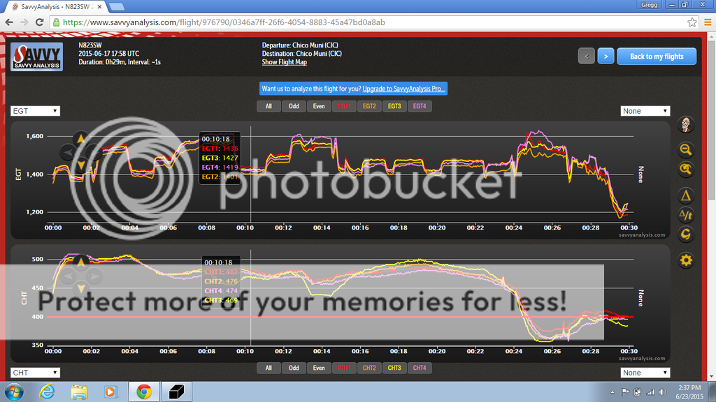
I'm posting graphs from Savvy of my last flight. The first is marked at peak EGT, the second is marked at full rich, which was 11.1 to 1 on the wide band AFR gauge and the third is just a graph of the flight with no marks. Please ignore the CHT temps -- there appears to be a conversion problem between the "J" type thermocouples on my CHTs, Savvy expects K type. Temps never got over 410.

Not sure if this helps with this discussion or not???

GEM


egt%20at%20peak.png.html


egt%20at%2011to1.png.html


egt%20full%20graph.png.html

Always interested in flight data. :)
 
Back
Top