What's new
Van's Air Force

Don't miss anything! Register now for full access to the definitive RV support community.

Modifying the stock battery tray for dual batteries

Carl Froehlich

Well Known Member
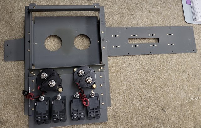
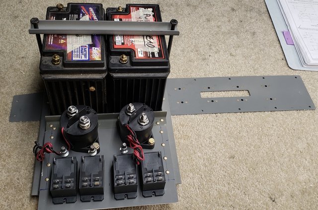
Just finished modifying the new RV-10 project battery tray to hold two PC-625 batteries (same as I did on the first RV-10).

Not hard, just need to make the U shape tray flat, add some 0.063” channel and a piece of 0.063” plate to hold the two Master solenoids and four 30 amp relays that feed both primary and alternate power to Avionics #1 and Avionics #2.

Carl
01843027-0-BFA-4-AF1-BC3-A-AF7304-DF29-BB.jpg

A42193-AA-4-DBC-4688-A9-A4-4-B243-A45-B362.jpg
 
This supports a three buss design:
- Non-Vital (the stuff that gets power from the master solenoids). This buss provided engine start power, connects the output from the alternator, and feeds those loads not needed for continued IFR flight (Landing Lights, NAV/Strobes, Pitot heat, etc.).
- All other loads are divided between left and right Vital Busses. These busses get power from these 30 amp relays (the only need 100ma to stay closed so a lot less drain as compared to a typical master solenoid). Each buss has a “Normal” and “Alternate” battery selection - so two relays are for Normal, two are for Alternate. Only one relay per buss can be turned on an any given time.

The POH is written to open both Master Solenoids on any electrical problem, this disconnects the “fat” wires from the batteries. Restoring the buss from one or both batteries is then a pilot decision based on indications. If not sure, the batteries will provide ~3 hours off full IFR flight to allow for trouble shooting on the ground.

Think of:
- Left Vital providing power to EFIS #1, COMM #1 and such.
- Right Vital providing power to EFIS #2 and Comm #2 and such.

The objective is to gain redundancy by providing mitigation for likely single point power system failures. This also eliminates the need for any backup batteries.

Carl

I did something similar based upon this approach. I have 2 batteries, 2 master solenoids for main buss, 2 30 amp relays for the avionics buss and 2 10 amp relays for the ignition buss. Each buss has both an on-off switch and a SP3T switch that allows for L - R - BOTH batteries. Normal operation is BOTH, but can customize load distribution with an Alt failure. The SP3T allows for switching from the BOTH location without breaking the connection. I can easily change power distribution without power interruption.

Larry
 
Last edited:
I see one issue: if you turn off the master solenoids, you have the alternator still connected to your "non essentials" without a battery to buffer the alternator voltage peaks. That might destroy your strobes, pitot heat etc.
 
Back
Top