What's new
Van's Air Force

Don't miss anything! Register now for full access to the definitive RV support community.

Exit Drag Testing

Earlier on I did some cowling pressure checks, not as elaborate as what these fellows are doing but it did help me get my head around what was happening.
In speaking with John Huft (currently fastest RV8) and Paul Lipps regarding the Coanda effect I made some fences in the bottom of the cowling to collect the air and deliver it smoothly to the outlet as shown in the picture below. Also note the almost closed spinner plate, the foam lightly rides on a thin layer of plastic tape that is on the prop shaft. I replace the foam about once a year, it is door and window frame sealant. Although the picture does not show the inlets they are very smooth and mate tightly to the baffles. On the upper left you can just see the outlet for the oil cooler, on the outside of the cowling I have a bluff body, CAFE inspired, that seems to work well. I would like to be able to duct the cooler down to the rear outlet but in my rocket there just is not enough room. The cowl flap is there but never needs to be opened. There is a sweet spot that is just shy of closed where everything seems to work best. I really should just glass the thing closed in that position. Note how far the cowl flap extends aft of the firewall. I have no heating problems in climb, but then I do live in Canada eh!
URL=http://imageshack.us/photo/my-images/813/img1878g.jpg/]
img1878g.jpg
[/URL]

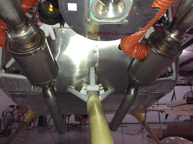
In the next picture you can see what goes on aft of the firewall. It is all about straightening the airflow, there is a fence on each side of the cowl exit and another right down the middle that does not show well in the picture. The small tube you see there is the sump drain for the throttle body. The black 1' tube is the crankcase vent. The aluminum plate goes from the bottom cross tube of the forward engine mount, back over all the hoses, back engine mount and extends aft about 18" The curved duct of the cowling mates up against this plate when the cowling is in place.
I have no idea what if any speed gains are attributed to this installation. I know that racing flat out I do not have any temperature issues. It would be nice to be able to do one change at a time, but that does not really work with my schedule. Hopefully we will be able to get some valuable information from the measurements that are being taken by the individuals in this thread. Before doing all this work, three winters ago, I looked at all the fast planes, RVs and glass, and noted that smooth flow, everywhere, was what separated them from slow planes. That was my mission and there is more that can be done. Currently I am running at my personal race speed limit, and all future gains will be made with cross country efficiency in mind.


Uploaded with ImageShack.us
 
Last edited:
Bob

I don't care if I can't construct a knowledge model to base success on. A concept proven by testing is good enough for me.

Agree completely and that is what I suggest. I guess it was this "is more tubulance and drag created when these two bodies of air come together around the entire outlet perimeter at one point than if the combination is in line with the exhaust pipes at two small points and some small area action takes place to stabilize those interfaces and and gradually spreads vertically and horizontally to the remainder of the interface" that confused me.

Fair the most turbulent, most offensive corners of the outlet and you will see a reduction in drag. Flow is so bad in this area that I am confident to say you will see substantially more than the .6 KT you need to get you over the 185KTAS barrier (and I will be very happy for you if I contributed even a little to that accomplishment).

I think my interest in the data collection is based on a belief that I might learn enough to judge how much improvement might be left. We'll see.

Hope you give it a try and hope it works. I know you'll share as you always have.
 
Holy Mackeral

While I'm typing Tom is contributing and sharing!!

There is so much here to absorb. I will say that seeing Tom's extended side fences at Airventure gave me confidence to believe I was on a good track.

Talk about concepts proven by results - here it is. Thanks Tom!!

Everyone else.... pick up your shears and get to it!!
 
Last edited:
Maybe Mike T can post results of toaster mod he made.
I know Bob mills is writing down notes.
Thanks for all info , Dan,Tom,Gary,Bob,Ken
 
Last edited:
This could be where the exhaust pulses could be used to speed up the exit air prior to hitting the outside free streaming air. Would probably require a bend in the pipes in the example shown, and having them cut a bit shorter.

I tried using my exhaust pipe as a way to add work to the exit flow. I didn't do much more than cut it shorter and shorter (in 1/2 inch increments) while measuring temp and airspeed changes (this was prior to all the instrumentation). Also added a ramp just aft of the exhaust. The only noticeable affect was a dramatic increase in sound both in the cockpit and from the ground. Even my neighbors noticed a difference. Eventually I had an extension made with a slight down turn and she purrs like a kitten again.

More could be done with the exhaust I'm sure.
 
Mike has to get rid of that ...

Maybe Mike T can post results of toaster mod he made.
I know Bob mills is writing down notes.
Thanks for all info , Dan,Tom,Gary,Bob,Ken

I think if Mike fared in the front of the old FAB inlet all the way to the cowl instead of bringing it to a point like a cow catcher he would do better but the new rebuilt engine sounds like it is bringing him up a few notches in speed. Maybe he is going to be competitive enough already. We will see at Sherman's North Texas Regional Airport on March 31st just 3 weeks off.

Bob Axsom
 
Tom is far too modest in his speed accomplishments. In fact, I'm convinced his greatest speed improvements he's keeping close to himself.

But I have been able to discern one:
flier1


I of course had to improve it: instead of 5" x 5". I cut it down to 5" x 4".

Cut the profile drag by 20%, still testing the results.;)

Everyone--Great discussion here, still noodling over the results and will pop them into some of my models.

Tom, now that your are solidly at Vne, time to think of a new frontier:

Time to Climb
 
Maybe Mike T can post results of toaster mod he made.
I know Bob mills is writing down notes.
Thanks for all info , Dan,Tom,Gary,Bob,Ken

Copious notes! I echo the thanks for sharing such great stuff! Looking forward to seeing the tests and results as they come in over time. Talk slow for me though, OK! Lot's of pictures! :cool:

Tom, I've never seen your motor with the cowl off...its quite a study! The lower plate mated to the ducting fences is artwork. In addition to smoothing and directing flow, do you think they play a similar part in separating upper (side) cowl pressure and/or flow from lower cowl pressure/flow, the way Bob Axsom's mid-cowl baffle material guards do (I think that's what they are designed to do).

I've been bouncing around ideas to add a radius to the lower corner of the firewall at the exit (like the 8's have, and as Gary apparently has...pics?), as well as a blocking device for the engine mount and accessory area, like yours. Seems to me that what you have there does both...you just moved the radiused coanda curve from the firewall exit lip to the forward crossbar of the engine mount. Perhaps that also helps the air exiting the aft cylinders to turn towards the exit, and thus bounce less off the lower cowl on the way to the exit (total conjecture). I'm wondering where the most effective place to have that coanda curve is...back by the firewall where air is accelerating (if it is accelerating there), or up where you have it, to aid in that acceleration towards the exit. No arguing with your success...just wonderin'.

Anyone have concerns (aerodynamic) about a fairly complete blocking off of the accessory area like this? Do we want to have the air back there have a path out, or is is such a dead zone or such turbulent flow, that its better to block it allow the exit air from the bottom of the cylinders to flow to the exit unfettered by air back by the upper and mid firewall? May have just answered my own question, but am thinking along the lines of that turbulent air trying to backflow somewhere we don't want it...dunno, just thinkin'.

The bottom aft fences on the belly really have my attention. When I saw your cowl flap and the sides of those channels in person, I actually thought you had built in a recessed ramp (like an 8). Now I see what you actually did, and its an idea that may work on any flat-bottomed fuselage. I have Gary's templates for his "exit trident", but that has been pushed back by new baffles, plenum and ram air mods. When I do get to it, I'll be weighing his and yours. Both appear to straighten flow nicely. His works perfect for a standard cowl opening, while yours may allow some Dan H-like variable exit experiments. Somewhere in between, my porridge may be "just right"! ;) Good tools to start with, and with the season coming up, Gary's trident, with an extension of my current cowl bottom to meet it at the firewall may be a great round 1 that can be done while flying.

Just great stuff to consider, and when I go at it, if I can figure it all out, I'll instrument up and take data as the others are doing...will re-read up on it, but I might, I mean will, need to ask more dumb questions about the equipment as I prep to do that!

I think if Mike fared in the front of the old FAB inlet all the way to the cowl instead of bringing it to a point like a cow catcher he would do better but the new rebuilt engine sounds like it is bringing him up a few notches in speed. Maybe he is going to be competitive enough already. We will see at Sherman's North Texas Regional Airport on March 31st just 3 weeks off.

Bob Axsom

Agreed...I know he's carbed, but seems a smooth-bottom cowl when using a snorkel would be better. I told him to add FI, and turn that thang into a ram air!

Tom, now that your are solidly at Vne, time to think of a new frontier:

Time to Climb

...or a turning race around pylons! :D

Cheers,
Bob
 
Anyone have concerns (aerodynamic) about a fairly complete blocking off of the accessory area like this? Do we want to have the air back there have a path out, or is is such a dead zone or such turbulent flow, that its better to block it allow the exit air from the bottom of the cylinders to flow to the exit unfettered by air back by the upper and mid firewall? May have just answered my own question, but am thinking along the lines of that turbulent air trying to backflow somewhere we don't want it...dunno, just thinkin'.


Cheers,
Bob

I have the area between the rear of the engine and the firewall fairly well isolated from the engine cooling air flow but the oil cooler dumps it's air in there behing cylinder #4. I have a 1/4" x 7" vent at the top of the cooling air outlet adjacent to the fuselage. The depth of th opening is set AN960 washers. Just to test it I stacked an additional washer on all four screws once and the test showed a decrease in speed. If that is accurate the size of the vent is sensitive. I do not have a volume limiting plenum independent of the upper cowl and the oil cooling air is a bleed of engine cooling air - there may be a clue there. There does appear to be a possible airplane speed sensitivity to pressure in the cooling system of our airplane.

I number my three inner cowl zones for easy reference as 1=upper cowl/plenum, 2=lower cowl bounded by the the rear curved baffle from the rear of the engine to just below the bottom of the fuselage, the two wedge baffles from the side of the cowl to the curved baffle at the width of the cooling air outlet and the horizontal baffle just below the cowl split (sealed with RTV to the valve covers and plenum baffle) and 3=the area behind these baffles between the engine and the firewall and the two long narrow areas outboard of the plenum baffles in the upper cowl. I already told you what happened when I opened the vent out of zone 3 that leads back to zone 1 via the oil cooler and blast tubes (when not racing). By the way, covering the plenum ports for cabin heat and blast tubes increased the airplane speed.

People here have mentioned seals at the front of the cowl around the prop shaft to elimimate that leakage path. I tried two separate approaches to do the same thing with baffles. One with several variations and one single shot test and remove. The one thing they all had in common was they started in the front a few inches aft of the front of the cowl and thus reduced the volume of zone 2 with no change in the volume of zone 1. Everyone of these made the airplane fly slower.

I have absolutely no problem with high temperatures of CHT, OIL or EGT in any flight mode but once in the stock configuration (no lower cowl baffling) while climbing out of Tucumcari, NM after a fuel stop heading west I had to lower the nose and richen the mixture to reduce the oil temperature and EGT (no CHT instrument back then).

I am also interested in the outlet flow fence mod and the lower outlet surface extension beyond the firewall mod by several in this thread. Unfortunately I have a lot going on in some other life areas right now but this looks very promising to me and I would like to implement and test a version before Texoma at the end of this month. Gonna be tough.

Bob Axsom
 
Last edited:
Nose Gear Fairing

If any of you have an idea or tip feel free to share.

This is a pic of the outlet baffle that I have to help direct the flow to the outlet in an effort to reduce turbulence/drag at the outlet.

My next step is to come up with a way to clean up the nose gear bracing.

IMAG0220.png


Currently can do 189kn WOT @ 885 Da (1000 agl).

goal is 195kn in the next 2 years.....???
 
Back
Top