What's new
Van's Air Force

Don't miss anything! Register now for full access to the definitive RV support community.

Pics of bracing back of GTN to subpanel?

sbalmos

Well Known Member
Hi all,

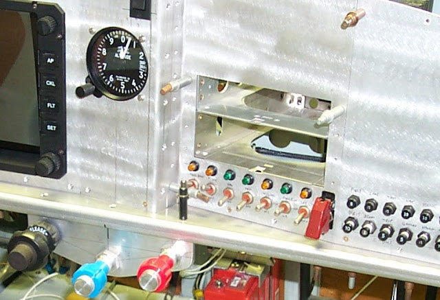
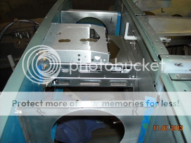
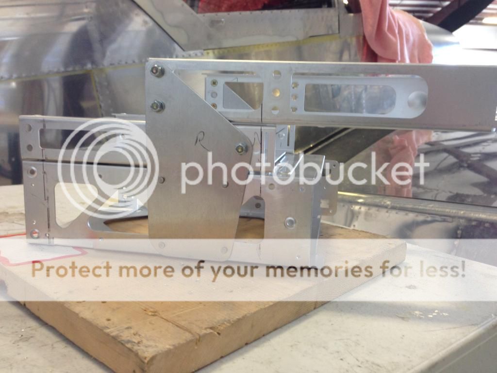
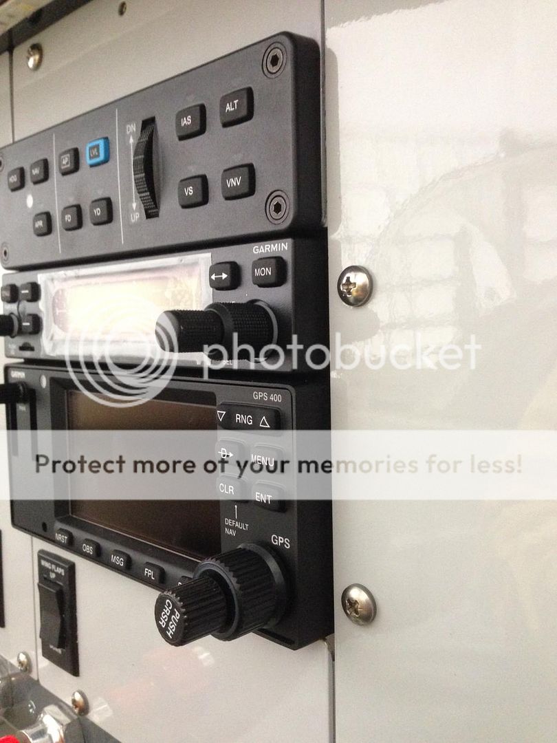
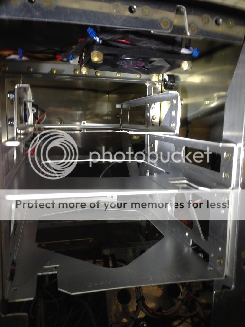
This is mostly directed to the RV-6/7/9 guys out there. I've seen how you brace the rear end of the GTN to the subpanel in an RV-8 (been bugging Jon Thocker a lot lately. :D). But in a 6/7/9, we have to cut a hole in the center subpanel for the length of the GTN (and really a GTR 20/200 also). I have a few ideas on what kind of angle bracket to mount to the subpanel in order to brace the rear end of the GTN. But I was curious for any build pics of how the rest of you have typically done it? Thanks!
 
I removed the support ribs and used the radio tray as a replacement sub panel support.

I used an .063 angle mounted to the GTN tray and used nut plates on the sub panel so I can remove it if necessary.

My glove box is below the GTN and I shortened it so it does not penetrate the sub panel. The angles act as supports for the rear of the glove box.

The audio panel on top is also short, so the only hole in the sub panel is for the GTN.

My canopy release lever is shortened so it is behind the audio panel tray and works only for maintenance should I ever have to remove the canopy. You can barely see it in the second picture through the audio tray.


8468088f-60ac-4efd-ba8a-870421d7e786_zpsjwk8fgzp.jpg


DSCN1096_zps253ee23f.jpg
 
I'm still trying to figure out exactly where I'm going to attach? the center rib to my panel frame. I have the affordable panels modular panel and its pretty busy in that area. That might be a good solution if I just removed it and used that rack as shown in the earlier post. I hadn't thought of that. But, I have my autopilot controller at the top so I only had to notch the rib to make it all fit. My problem is simply the attachment point. My fuse kit is to be delivered soon so I'll then have the skin to figure out the exact positioning.
 
Bob, that was one of my ideas, and actually my preferred one, to use angles attached to the GTN box and screwed to the subpanel. What I was worried about, because I hadn't gotten far enough visualizing or testing, is whether the GTN mounting box's side screw holes, to attach the angle to, matched up with the depth of the subpanel, so that a normal piece of .063 angle could be used.

Is that .063 angle a normal 3/4" leg length piece, or is it some other leg length?
 
... is whether the GTN mounting box's side screw holes, to attach the angle to matched up with the depth of the subpanel,...

You don't need to use the provided holes in the tray. Just drill some new ones where they need to be. You can back-countersink or even dimple the tray if you get creative with the dimple dies. Remember, the side screws in the rear of the tray (front of the airplane) only take up vertical shear load. The majority of the structural loads go through the face of the main panel. On the rear of my trays, I used 5/8 x .016 L-stiffener stock leftover from rudder/elevator/aileron construction. At the panel face, I used 3/4 x 1/16 angle, one piece each side, long enough to hold all the trays. I riveted the angles to the panel and used Rivnuts for the 6-32 flatheads holding the trays to the angles.

mitch1.JPG


P0001398.JPG


mitch2.JPG
 
The existing holes in the tray fit perfectly with the sub panel angle which is the standard .063x 3/4. Note that this is for a tipup and may be different for a slider.

Note in the picture, the sub ribs are cleco'd in place for spacing. They were removed when the cutouts were made for the Skyview panels.


DSCN1078_zpskllnhlrs.jpg
 
Thanks Bob. There are definite differences between tipup and slider, but depth doesn't seem to be one of them, since really the depth of the subpanel back from the panel is set by the forward end of the forward canopy deck and forward vertical bulkheads. Anyway, I eyeball-fit some 3/4" angle last night, and I would agree it looks like it works. We'll know tonight when I cut the hole in the subpanel. :D

Thanks again!
 
Slider subpanel cutout for GTN 750

Marking for wire bundle cutout:

24ycjmh.jpg


Subpanel cutout (GTN 750):

2u6ftih.jpg


Angle brace being fitted to right side:

242zzo1.jpg


Wire bundle on left side:

1s0hfr.jpg


Hope these help!
 
Beautiful Melinda, actually was exactly what I planned to do tonight, including the wiring hole cutout. It looks like there's some form of clear anti-rubbing tape you put on the hole edges? I was thinking of lining my hole with rubberized tape or similar, to protect the wiring going through.
 
I really like Mel's use of nutplates on the rear angle on the subpanel, my 3/4 X 3/4 angle was riveted in and very hard to drill and install the little hardware in place. I ended up making a bracket in addition to the angle riveted to the subpanel. The top rack is pushed back for the remote transponder behind my autopilot control panel. Just picture one hand and an angle drill inside the radio racks with the other hand trying to hold things steady while hoping to drill things straight into the riveted angle. Not to mention how many times I dropped a washer or times I flipped the open end wrench around because a box end/socket wouldn't fit.
6507592D-5F5E-4BFA-9E34-F15950F8CEFF_zpslmqwsn4y.jpg


B8A76DB2-739F-4755-ACEB-B5070F80B2CF_zpscbzwoy0t.jpg


While you are at it I would make the front angle 1 1/2-2 inches wide, mine was 3/4 X 3/4 and it wasn't deep enough ( I had to remake them). It also depends on how you mount the face, mine kinda stick back in the panel further than some I've seen. Also I found the tray/bezel on the avionics aren't the same size, I had to stagger the trays slightly to get the faces to line up.

31294FA7-98C7-43A1-92BE-23C2C6FD196D_zpsjwm7hz9c.jpg


606DA83E-602B-4A0C-AAC0-DB31D1B342C5_zps5eghelmp.jpg
 
Yeah, the front I'm not worried about. That front angle was cut and drilled by Stein's guys, so everything already aligns up front. Just dealing with the back supports. Even better is it looks like I might get lucky and not have to do any mod'ing to the center rib, based on the depths of the GMC and GMA.

Here's how the panel stands so far with everything in.

bCOgavVNJvGDsi6hVshvh7MCRVW9hRGNQq9oZBChrvNpbWzAUZIQi1vKxAq3y1BxXWyovcV7jxdvQVTULQEFAOBTSeaqRMsNn6TG77nr3CYJtom-pcKs9wWn3wS6A_3cLRMn_r5iMSetj9KlO8ZTPOQf77IuhXKWPILf6_uCU4VajiV2dbUw9RgFtHTZdFn5skr5UrIXeSOWhYugj9nFCyE3Ngnkaex7YhQwQ4tDoCSVVw7GUkVbtkU5y4PK-YcBUjPoiQOwXVgwvN29-e-bVEea4ePbVawp4TCRENC_-Ycz8ggCHN6PHow55QkwEEWPeDZAQ1Vn92t4PQCrRW4Kt81Im7skbM_z8TX5jTgc4ut1RJ6hEg6_ACA02B_JtigHNqykfk8FbtodCQ5vV_Tas26tnB8cJndXj-tc7SAq9sqrJJ0pbW8AGxJRBnadvgDmX4FBY87AZZXLpGC5IbnrH_n7yKbSNXOwAfmUTloiwELX3nqaYioFy-2YCjXpthdwtu_YvpLW_1tvb3uhEoHAuZabSqXloE-3xk6NXWkIhU4Ke-etxGJNuUzkkMZ0vU0u3VVY=w1122-h634-no
 
locating and cutting the hole in the subpanel is the tough part. I think I used some framing square or something from the front panel to project the location on to the subpanel. Make it a 1/4" oversize than butt some angles off the rack to the subpanel.
 
Back
Top