What's new
Van's Air Force

Don't miss anything! Register now for full access to the definitive RV support community.

Cowl exit size

erikpmort

Well Known Member
Can you six owners take a quick measurement for me ? I'm still trying to figure out how to reduce my cht temps. I break through 400 even in this cool air on climb out- even at 120 mph and less than wot settings.

I want to try to open my cowl exit hole a bit. I have heard of success with that. I read some other old threads and checked to see if I have the cowling upper ramps and I do. I wish I would have been smart enough to see this when I bought it but was not. I'm sure there is a reasonable answer to my problems however. It is a very standard setup. If it's helps the hot cylinder is number 4 though sometimes it's number 3. Thanks
 
I think I would check out all other factors before I started modifying things.
There are literally thousands of RV-6s flying with the original cowling and no problems.
Is your engine newly overhauled and not broken in?
Do you have the baffles sealed properly around the engine and the cowling?
Is your temperature gauge calibrated?
Have you had another RV builder check it out?

Typically #3 is the hottest cylinder on RVs.
 
Last edited:
How do I check for calibrated sensor ?

How do you effectively check the seal of the cowl? I know that's a newbie question but seriously. Through the oil door ?
 
Do a search on this site or Matronics for "air dams". They are little air deflectors which (when properly sized and placed) can really help balance CHT's.

I will add that there are few circumstances that require extended climbs at < 135 knots. You might climb at Vy to pattern altitude, but after that, a cruise climb will keep your CHT's happier.
 
I have yet to look at someones RV (at their request) for baffling problems that could contribute to higher than desired temps, and not found some things that could be improved. Often times there is serious issues.
There are other possible causes also... such as advanced ignition timing, etc.

Like Mel said, you should know for certain that you have ruled out all other possibility's before you start cutting up the cowling.
 
The two most common causes:

1) Carbureted engine. Most carbed engines need to be rejetted for the RVs. You can test this by checking to see if you can get a normal EGT range in flight... from about 200 ROP to LOP as you lean the mixture in cruise. If you can't get a definite EGT rise, then your jet is too lean.

Most of the RV'rs around here need to rejet their carbs (we are at sea level).

2) ECI cylinders. Some engines (at least in the past) have cylinder flashings blocking airflow through the fins that are located between the spark plugs. Several hours and several broken extension drills and files will clean this up. Made a 40 deg F difference on my engine. I even had to touch up the Lycoming cylinders on my IO-540.
 
Erik,
You asked a valid question, in my setup on the 7 I have 4 pipes plus 3 rubber tubes wrapped in fire sleeve making a 1 1/2 bundle between the tubes. We checked all the baffling but like you could not climb out with out temps reaching
400 +degrees.
We figured that there was not enough exit area so I thought about increasing the exit area a little bit at a time.
Bought a louver from aircraft spruce and cut it in half so I would have a flange on both ends of the louver Eliminated one louver so they would have the same number of louvers there are 9 in the one piece.
Made a backing plate for both and installed them in the bottom cowling to each side of the exhaust exit. There is a flat area just to the side before the gear cutout that worked perfect.
Used a backset tool in the rivet gun to make the shop head while a friend held a bucking bar on the countersunk AN 3 rivet. Use low pressure you can squish the honeycomb. Used dolphin flailing compound to smooth the transition on the outside of the cowling and sealed the honeycomb cutout with fiberglass resin and flox.

The result was a 14- 18 degree drop in cylinder head temp and now during a 130 knot climb out my cylinder tems are running between 372 and 382 which is a lot less then the previous 403 ,410 readings.
I can do pattern work and stay way below 370.
I know the outside temperatures are cooler now but in the summer if I have to increase it again, I will add one more louver in the center back of the cowling.

Another tell tale sign was between the skybolt fastners the top rear of the cowling were rising up...this has almost been eliminated. Van has since changed vendors for their pink cowling. If I had used the piano hinge probably would not have noticed it.
I also saw Larry Vetterman's cowling with a 4 pipe system and he put louvers in.

Smilin' Jack
 
Last edited:
Erik, take a day and come north, I'll take a look at it and you'll get to do some flying. KLGU-8U8 is only 273(easy RV)nm.

I had high CHT's, over 400*, the first year flying mine. I have a IO-360 with 9:1 compression, 4 pipe exhaust and a Sam James cowl w/plenum. The James cowl has a smaller cowl outlet than Vans cowl. I added a outlet ramp to help smooth the flow leaving the cowl and located every possible leak path in the baffle/engine plenum interface. Drop my temps about 20*.

I'm betting there is a place for improvement in your baffle area.
 
Brian,

FYI and a little off topic here, but, I have a long SJ cowl, and the standard Vans cowl. I measured the outlet area of the two (uninstalled) and they are identical. Both are for carb engines. I noticed yours had a different engine intake axis so I talked to Will James. Since I have an IO now, Will was kind enough to make be a new inlet including the transition all the way back to the cowling air exit. Surprise! The exit area of the IO cowl is indeed less than the "O" cowl. I will measure it tomorrow and post the dimensional differences.

Your smaller area and successful cooling ( with more HP) should be confidence building for Erik's cooling challenge.
 
Ok

Brian, thank you I think I will take you up on that offer. I have one Rv friend here and he is a nice guy but not a builder so I am lacking a bit of expert Rv experience to draw from locally. Haven't been north of Jackson yet so that sounds like another good excuse. Thanks for the responses by the way- this thread is getting good. Can anyone post pictures of the exit ramps they have made ? Thank you !
 
Erik, If you want to come this way some time, just let me know. I have a flexible work schedule so can usually be available with a little notice. I could come down there even. My daughter lives in Kamas, so we end up in Heber(36U) once in a while.
 
Brian,

FYI and a little off topic here, but, I have a long SJ cowl, and the standard Vans cowl. I measured the outlet area of the two (uninstalled) and they are identical. Both are for carb engines. I noticed yours had a different engine intake axis so I talked to Will James. Since I have an IO now, Will was kind enough to make be a new inlet including the transition all the way back to the cowling air exit. Surprise! The exit area of the IO cowl is indeed less than the "O" cowl. I will measure it tomorrow and post the dimensional differences.

Your smaller area and successful cooling ( with more HP) should be confidence building for Erik's cooling challenge.

Bill, here's a thread from long ago about my cowl outlet before I flew. I haven't done much to it yet.


http://www.vansairforce.com/community/showthread.php?t=53303&highlight=cowl+outlet+ratio
 
Erik,

Some great advice from the gang here. I agree that looking at other possible solutions is a good first step, prior to opening up the exit or adding louvers. Both can be effective in decreasing temps by increasing cooling air mass flow, but at the expense of increased cooling drag. However, if baffling or plenum leaks are present, you may make cowling changes and be disappointed with the lack of results...so check the baffles and other mentioned areas first.

How is your oil cooling? That can be a factor too...engine cooling and oil cooling can impact each other.

Bob Ashmore is a builder (7) down at Ogden, and there is a very robust RV presence at OGD. Some good expertise to tap into there! Brian will be a great mentor too...he'll steer ya straight! If you find your self near Reno, same offer applies...we have some smart cookies here too, and my hangar neighbor is a bit of a building guru. Holler if you're out this way.

On the other side of the coin, check out Dan H's thread "The Shrinking Exit", which shows how small an exit can be and still cool adequately...when the rest of the cooling system is squared away, like his is. Also, Dave Anders showed great success at about 76% outlet to inlet area. I emulated their work, to a degree, and reduced my 6 cowl outlet from larger-than-stock to smaller-than-stock, and went from over-cooling to adequate cooling...with a 540...so it can be done without opening the cowl exit up prematurely.

Good luck with the chase...it'll be gratifying when you work it through!!

Cheers,
Bob
 
cowling exit

I came across posting on VAF some time back were a member added a 1.5 to 2 inch roll over exit and said it helped with cylinder temps 15 deg. I think the RV8's have that in the kit any pictures on that mod anyone could post as I want to try that mod on my RV6.
Thanks
Bob
 
Erik, There are lots (most) RV running around out there with good temps and stock outlets. As has been suggested here, with everything else "right", the stock outlet is generous. By all means check everything on the cowl/ baffles etc. Make sure they are "right".

Do not underestimate the importance of ignition timing!!!!! Advanced timing will have a huge effect on Temps (CHT and oil). Timing can change over time. Before any further work, double check the timing. 25 BTDC for stock compressions, less for higher compression. Even 2 degrees more advance than necessary can elevate CHT's 20 - 30 degrees easily, especially at high power settings.
 
First, the guys like Gary, and Mel and others that have mentioned timing are shmart fellers, and that can be a hidden item. I've seen racers bump their timing up just a degree or two, and then have to back off in a race, due to high CHTs. And baffle/plenum leaks are like a missing batt of insulation in your home…a small gap can make a large temp difference. Good things to check out!

For Bob:

I came across posting on VAF some time back were a member added a 1.5 to 2 inch roll over exit and said it helped with cylinder temps 15 deg. I think the RV8's have that in the kit any pictures on that mod anyone could post as I want to try that mod on my RV6.
Thanks
Bob

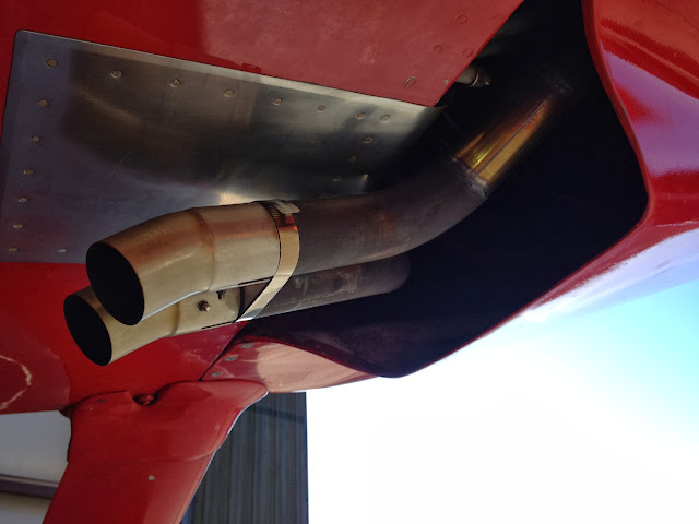
I did that firewall radius mod last winter, as part of an exhaust reshape and cowl exit reduction experiment. My overall goal was to reduce cooling drag (mass flow) by reducing exit area, while adding the radius to help smooth the flow at the exit, and help streamline the flow with the ambient air flow. I wanted less mass flow, but more efficient flow. I was overcooling with a very large exit, so I was willing to accept slightly higher temps in trade for overall speed and efficiency. This is opposite of what Erik is trying to achieve (cooler temps), but I'll circle back to that at the end.

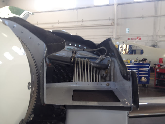
The radius was highly recommended by Steve Smith, who gave me a great deal of good advice in this project! Because I also reshaped my exhaust pipes to be closer together and angled down less, I continued the radius into a SS belly pan, which was recommended by Dan H (much thanks to Steve and Dan for their great ideas!).

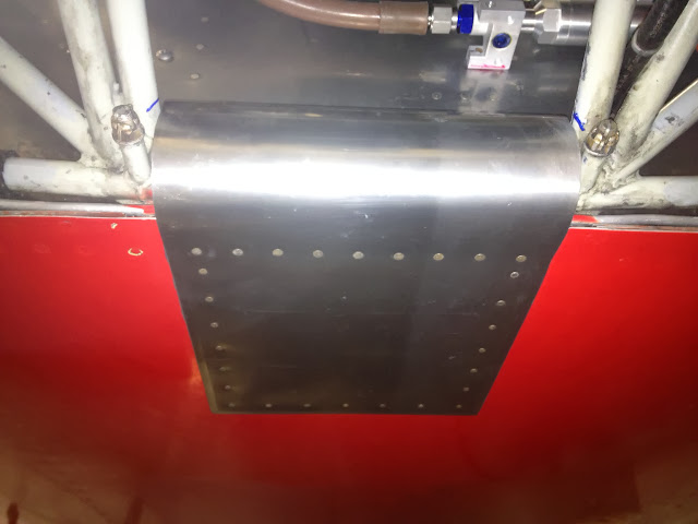
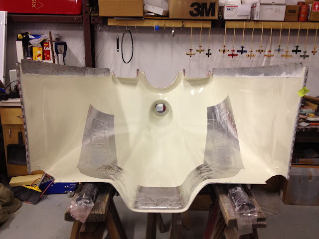
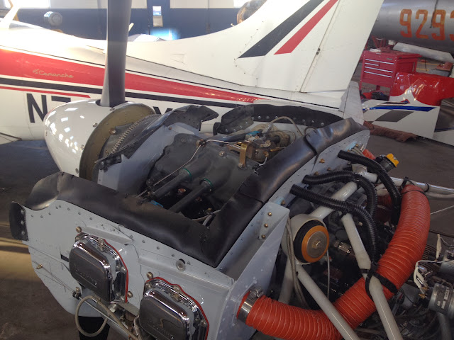
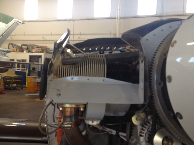
The width of my firewall radius and my new exit opening was constrained by the custom engine mount for the 540. Both are limited to about 9" wide by mount tubes.

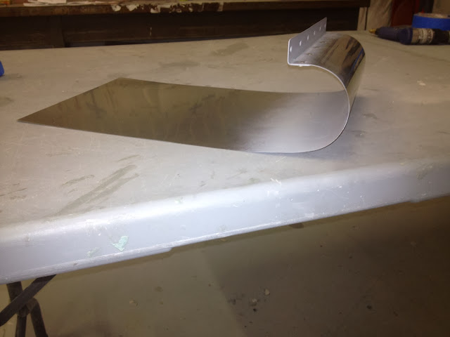
I formed the SS sheet into a radius by rolling it with a PVC pipe, much like we do with the rudder leading edge. I was shooting for a 3" radius, and got lucky (very lucky relative to my fabrication record of scrap generation! :eek:) Added a flange to attach the radius to the firewall.
IMG_0111_2.jpg


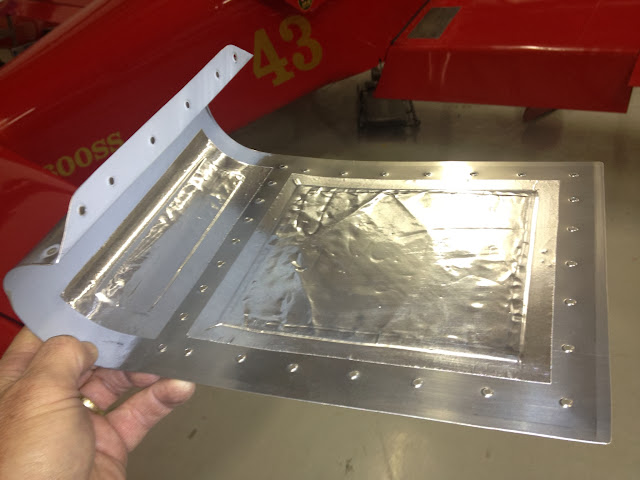
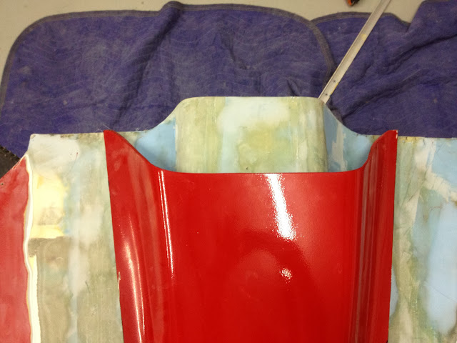
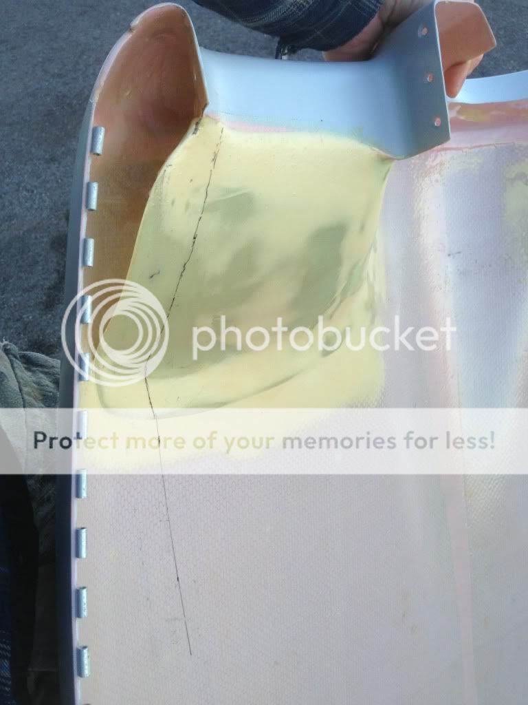
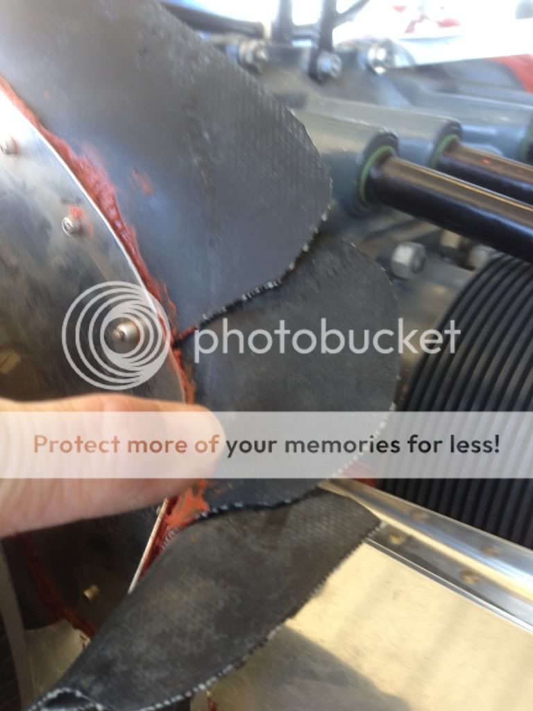
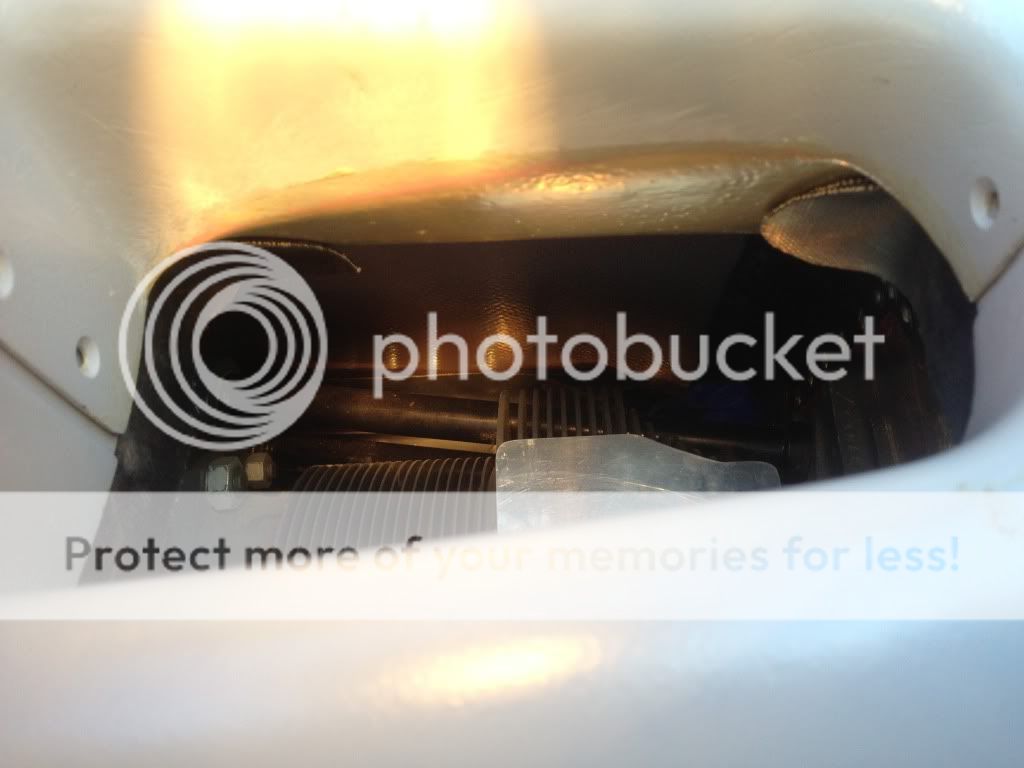
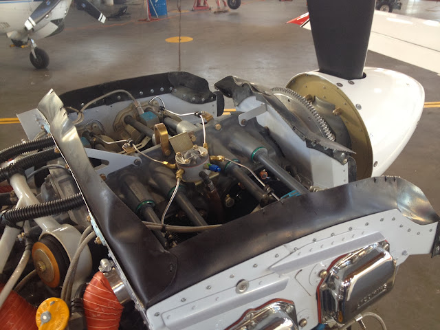
I was pretty aggressive in my exhaust reshape, and the pipes now have only about a 10-11 degree down angle (ala Paeser), so I added fiberfrax to the areas where the pipes passed the belly pan, taped in place with cowling heat tape:
IMG_0142_2.jpg


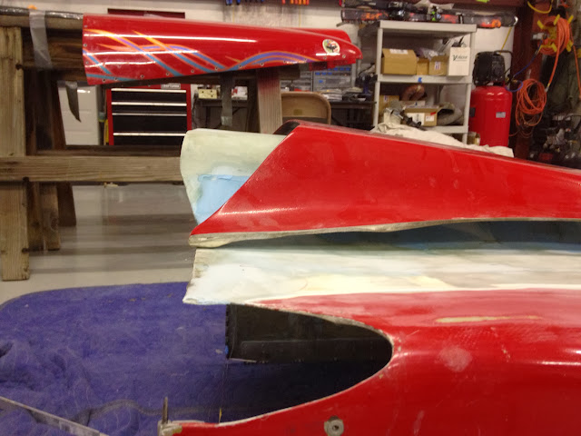
I covered the belly pan with proseal before riveting, to try to seal the interface from air leaks and oil that might wick into the fiberfrax or the heat tape. Just wanted a nice tight fit. The edges were seamed with a roller seamer too.
IMG_0145_2.jpg


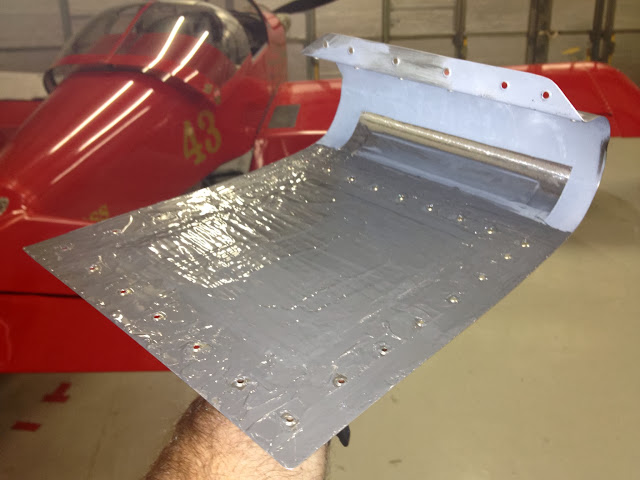
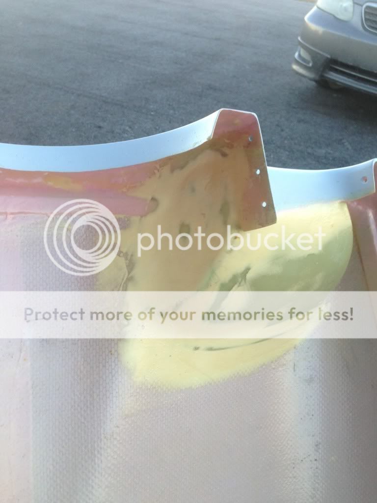
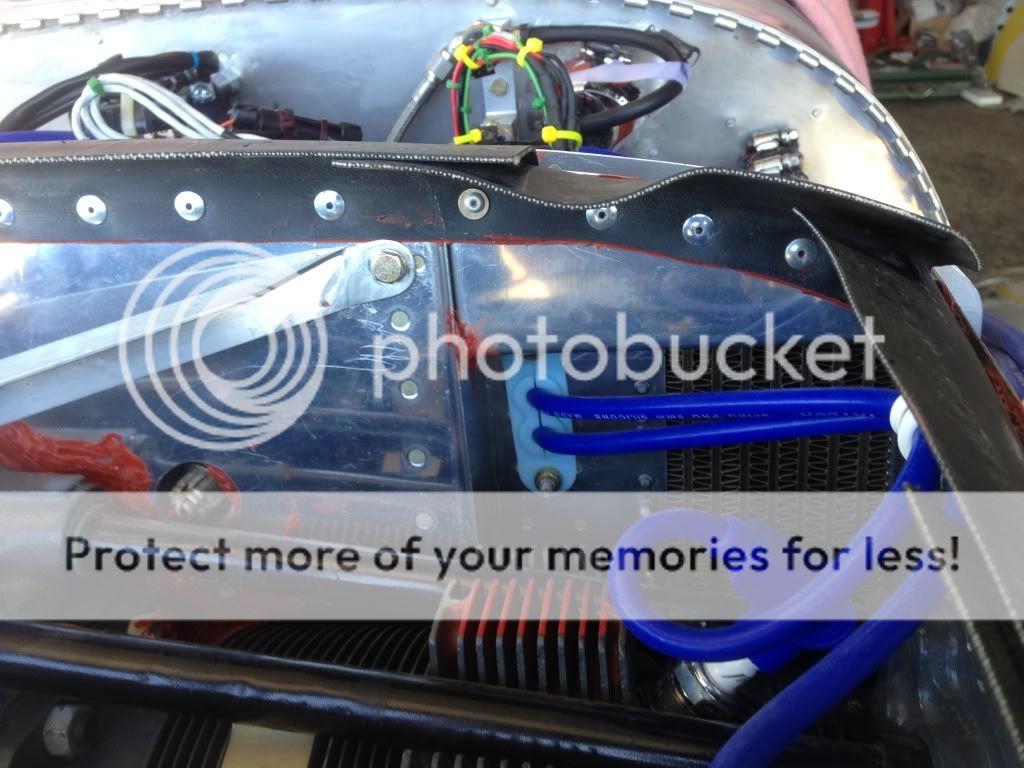
Then it was match-drill (to the holes where I drilled out the rivets in the floor ribs), cleco into place and rivet:
IMG_0130_2.jpg


IMG_0151_2.jpg


Though I did rivet the upper flange to the firewall (for which I have been flogged by F1Boss Mark), I would use #10 CS screws were I to do it again, for engine mount inspection and serviceability (I'll be drilling those out and replacing them). That might not be a factor for standard 6 mounts, if there is no lower cross tube.

I flew the plane with the new radius and the old, larger exit on a X-C to a form clinic. Steve and I discussed the possibility that I might see slower speeds due to increased mass flow, thanks to the firewall radius, before I reduced the exit area. I did not do a 4-way test (time and weather constraints), but I did not see a slowing on that X-C with just the radius added. CHTs were cooler, but (big but), it was extremely cold on the X-C, so cooling would be better, and X-C speed might be enhanced by the temps. It may very well have been a little cooler and a little slower on a more normal OAT day. The firewall radius could very well have increased mass flow, which would be the expected result. I just can't prove it.

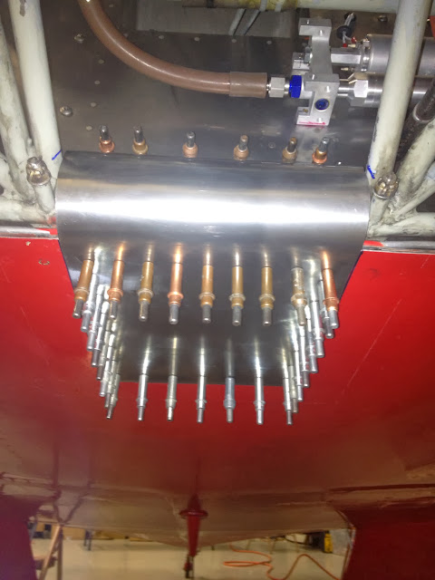
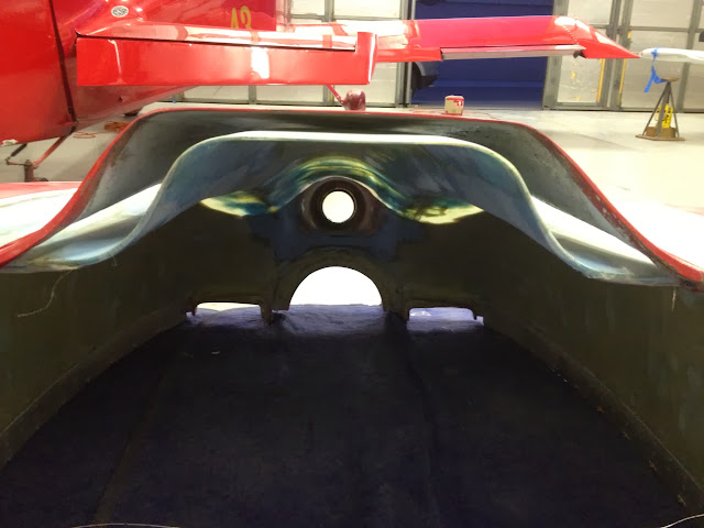
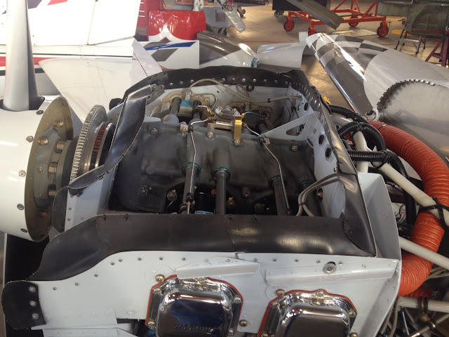
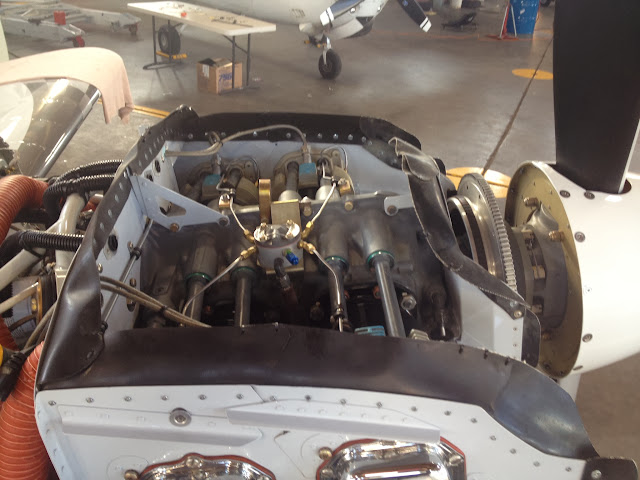
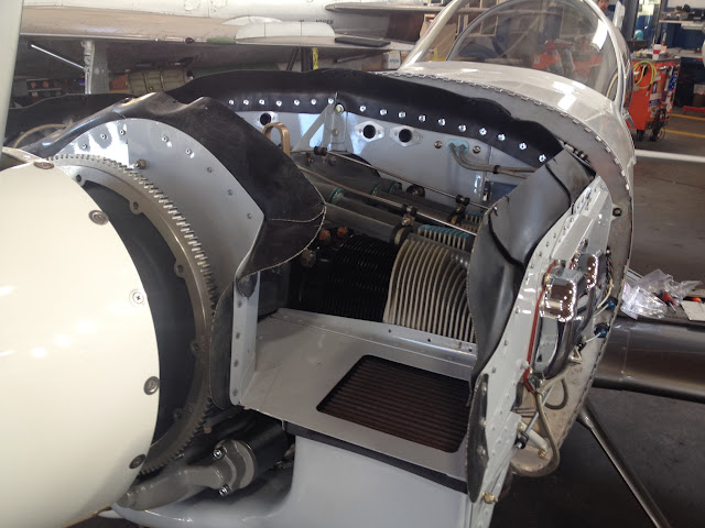
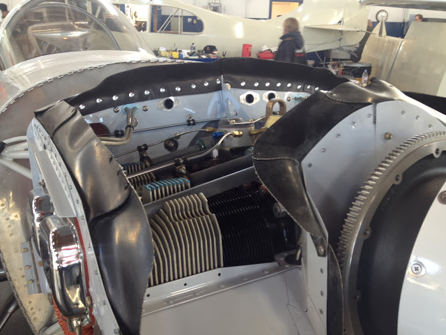
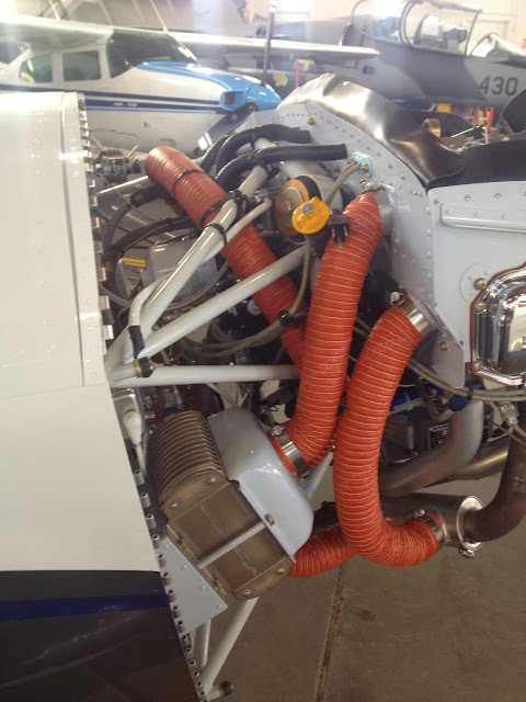
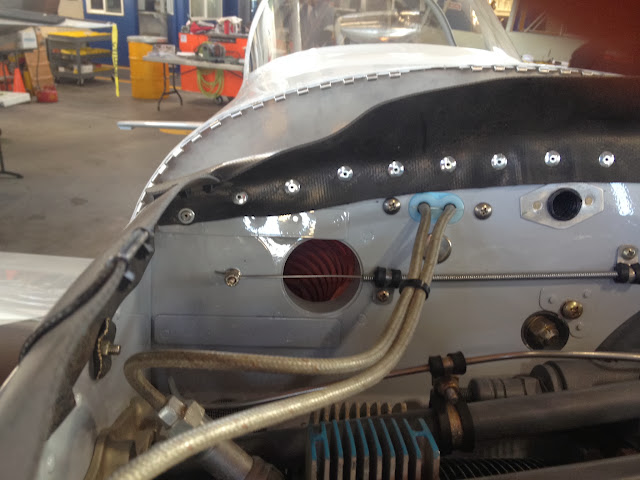
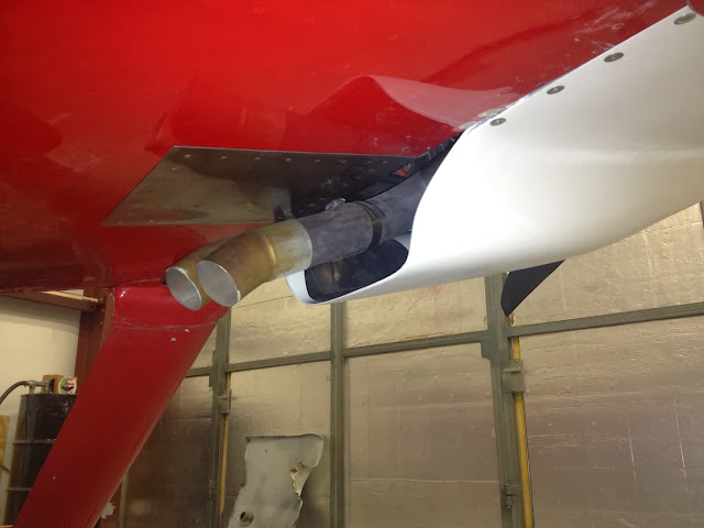
However, once I did reduce the exit size (phase II of the project), I did see higher temps and increased speed…both indications of decreased mass flow. I do see much more streamlined exhaust and oil flow lines on the belly (mostly exhaust). I no longer see evidence of reverse flow, as I did pre-mod. Here are a couple pics. First is the new exhaust shape and SS firewall radius, but old cowl opening; second is with new cowl exit shape (pre-paint). For the numbers guys, I went from about 1.8:1 exit to inlet (yes, that big!) to about .75:1. Temps are higher, but manageable, even in races…though challenged by a formation show at 107F (go figure!). Speed… +6-8 knots (honest! multiple tests and races show it). Going smaller will require a cowl flap, and I've got some skill-building to do to match what Dan did on his 8…but its under consideration! ;)
IMG_0157_2.jpg


IMG_0534_2.jpg


So Bob, I hope that helps on the radius project…holler if you want more details. I'm glad you brought it up here, as it may be another consideration for Erik (the radius by itself could increase mass flow and help cool the engine)..., once you check out (as Arnold would say), "za timing, za baffles, za flashing, za inlet ramps, and so on, and so force". ;)

Cheers,
Bob
 
Last edited:
Nice work Bob.

Suggestion: before you paint, extend the exit glass rearward about 4" past the firewall. You'll probably need to build with a flange on each side so you can use another couple fasteners into the belly to support the extension. This is the -8 version; you can see the extra screws, two on each side:

5cgfih.jpg
 
Exhaust pipe

Dan did you paint the inside of your exhaust pipe and do you wash it after each flight.
Bob
 
Nice work Bob.

Suggestion: before you paint, extend the exit glass rearward about 4" past the firewall. You'll probably need to build with a flange on each side so you can use another couple fasteners into the belly to support the extension. This is the -8 version; you can see the extra screws, two on each side:

Thanks Dan! I've already painted it, but have sandpaper and an airbrush, and a willing mind (crazy as it may be!). I've looked at that picture many times, as well as its compadres on the Shrinking Exit thread. Much inspiration (and perspiration ;)) came from them! I agree, further back would be better. It was a shortfall of my mold-making! My current version extends about 1" aft of the firewall, but I like your idea, and Tom Martin had similar advice back when I was contemplating the original mod. If I could have figured a way to keep the glass from collapsing on me back there…

Here are a couple comparison pics of old to new cowl:
IMG_0439.jpg


IMG_0433.jpg


IMG_0432.jpg


Now that the pipes are flatter (higher), I can extend the cowl further aft, as you suggest. I actually think I can raise the bottom a bit more (to decrease the area a bit more), but have to be careful about the geometry…it took two versions of this to clear the exhaust pipes at the concave corners! :eek: I may be at that point (area-wise) where smaller will require the complexity of the cowl flap, but provide small relative gain. Been mulling that over a lot! I may actually experiment with AL shaped to match the exit, then bonded to the inner face, and extending aft to near where the turndowns bend. Are you still happy with the heat resistance where the glass very close to the pipes in the pic? I also used fiberfrax and heat tape near the pipes, but 3/4" is about my closest point of approach:
IMG_0516.jpg


Really appreciate the feedback…winter mod season is on!

For Erik and Bob, some of these items could help each of your situations. Erik, maybe you could post pics of your cowl exit, on and off, as well as some of your baffles and oil cooler set up. For Bob, I know you are trying to flow more air, so maybe post pics of your exit. Maybe the brain trust here can provide some thoughts on how to incorporate a radius or improve the cowl shape.

Cheers,
Bob
 
Last edited:
I may be at that point (area-wise) where smaller will require the complexity of the cowl flap, but provide small relative gain.

Small relative gain? Keep talking like that and they'll take away your racer card ;)

You still have a lot of room to pull the exit opening tighter, but yes, climb may then require additional exit area you control.

Are you still happy with the heat resistance where the glass very close to the pipes in the pic? I also used fiberfrax and heat tape near the pipes, but 3/4" is about my closest point of approach.

Just had the cowl off for annual, and it's all doing fine. The only sign of heat damage is where the forward edge of the door previously tipped upward into actual contact with a pipe. Changed that when I switched to a T2-7A servo. FWIW, recall the current exit panel was built using an epoxy with a higher Tg than West.

Erik, maybe you could post pics of your cowl exit, on and off, as well as some of your baffles and oil cooler set up.

Yes, we're drifting away from the OP's issue. What can you show us Erik?
 
Last edited:
This is not all that complicated nor does it require a major cowl modification.
Lower cowl pressure can be reduced and thereby increasing air flow by extending forward the standard 3x14 opening a couple inches. That will help solve the problem and may be all that is required.
 
This is not all that complicated nor does it require a major cowl modification.
Lower cowl pressure can be reduced and thereby increasing air flow by extending forward the standard 3x14 opening a couple inches. That will help solve the problem and may be all that is required.


And I agree, It's not complicated....If fact does NOT require any cowl mods. NO cutting or louvers.

The is a very good chance Erik has plenty of airflow, it is just not flowing in the right places. Plugging and cleaning up the path of the air might be all he needs.
 
This is not all that complicated nor does it require a major cowl modification.
Lower cowl pressure can be reduced and thereby increasing air flow by extending forward the standard 3x14 opening a couple inches. That will help solve the problem and may be all that is required.

No one is suggesting Erik needs a major cowl mod. Bob was merely demonstrating that it is possible to shrink the exit and still have adequate cooling, if care is taken with the rest of the system.

Increasing exit size is a lot like the old Dear Abby advice about finding a husband; any girl can get married if she sets her sights low enough.

Abbey generally did better than that.:)
 
Small relative gain? Keep talking like that and they'll take away your racer card ;)
Laughed hard at that?and you are spot on?I wouldn't pass up a knot, like an airline pilot wouldn't pass up a free paper! :D Pls see next comment.

You still have a lot of room to pull the exit opening tighter, but yes, climb may then require additional exit area you control.
I think I'm right there, and any more reduction will require a cowl flap. it means I haven't gone small enough, since the perfect place is probably a bit too small for anything but racing, or maybe cruise, and any slower requires opening the flap a bit. But?contemplating cold air/forward facing and an AFP servo, even a 6:1 exhaust. That will likely be a major cowl mod too, with even more emulation of your system. 1200 hours on the motor, so may hold that off till overhaul too. So I'm juggling, and a small tweak may be a good short term project, to continue the experiment! But I'm not ADD?I think?:rolleyes:


Just had the cowl off for annual, and it's all doing fine. The only sign of heat damage is where the forward edge of the door previously tipped upward into actual contact with a pipe. Changed that when I switched to a T2-7A servo. FWIW, recall the current exit panel was built using an epoxy with a higher Tg than West.
Good info, thx! I'm learning about Tg from Steve?what product do you use? Going that direction will be needed to get closer to the pipes!

Yes, we're drifting away from the OP's issue. What can you show us Erik?
Agreed?Erik, how can we help ya!

This is not all that complicated nor does it require a major cowl modification.
Lower cowl pressure can be reduced and thereby increasing air flow by extending forward the standard 3x14 opening a couple inches. That will help solve the problem and may be all that is required.

And I agree, It's not complicated....If fact does NOT require any cowl mods. NO cutting or louvers.

The is a very good chance Erik has plenty of airflow, it is just not flowing in the right places. Plugging and cleaning up the path of the air might be all he needs.

No one is suggesting Erik needs a major cowl mod. Bob was merely demonstrating that it is possible to shrink the exit and still have adequate cooling, if care is taken with the rest of the system.

Increasing exit size is a lot like the old Dear Abby advice about finding a husband; any girl can get married if she sets her sights low enough.

Agreed, that is a simple fix, though I've seen it not be that effective on a 7 that Smokey and I did that very thing to. That one was primarily an oil cooler issue. That technique was used on my original cowl by the builder, as you can see in the pictures. It cooled great, but at a speed/efficiency cost. Its an arrow to keep in the quiver, but I'd save it for somewhat of a last resort. Not a slam, just MHO.

Abbey generally did better than that.:)
You guys crack me up! The letter would be from "Too hot to handle" :p

Cheers,
Bob
 
Exit Area RV6/7, SJ Cowls.

I promised to post the area difference between the SJ O-360 and SJ IO-360 cowls.

1. The outlet area of the standard RV7-6 cowl and the SJ-O cowl is/are the same shape and area. 4 5/16" tall and 13 5/8" wide at the center of the trapezoidal shape. This is 58.8 in^2.

2. The base width of the SJ-IO cowl is the same as the RV7/6. The "height" is reduced to 3 1/2". Since the angle of the sides of this trapezoid is the same and base is the same, the center width is increased to 13 13/16". This makes the open flow area 48.3 in^2. It is 18% less than the standards in #1.

So, HydroGuy, if your dimensions are like above, then your external cross sectional area is reduced as well as the cooling exit flow area by 10 in^2 compared to the "standard". I don't know if this is by design from SJ, but it might contribute to the cooling challenges of some SJ -7 builders.

I make no claims that all cowls are made the same, this just what I have on hand.

Sorry for the delay, got sick, well and diverted.
 
Those numbers sound about right. Then I have 4 pipes poking through there also, which reduces the actual area.
 
Excellent...real measurements. Thanks Bill.

May I assume the referenced IO-cowl is intended for an angle valve motor?
 
Excellent...real measurements. Thanks Bill.

May I assume the referenced IO-cowl is intended for an angle valve motor?

Sorry Dan, I don't know the SJ product line that well. I have the full length "O" cowl but switched to an IO360 Parallel engine. My horizontal servo is higher than the "O" cowl inlet scoop AND the shape is different. I called Will James and we was kind enough to make me that portion of the cowl with the scoop continuing back to the air exit, so I can just cut and paste it into my cowl. He made this section right off the full mold. Will offered to swap the full lower outright, but it was cheaper to buy and ship the partial cowl than shipping cowls between IL and WA state.

So - I can say it is for the parallel, but don't know that the parallel/angle cowls are different.

PS - I looks like I will be getting a lot of glass experience, not a bad thing.
 
Baffle pics

http://s412.photobucket.com/user/erikpmort/library/?view=recent

Well I don't know if pictures are going to be much help but I hope so.

It's cold enough now that I need to be worrying about taping off the oil cooler- couldn't break 130 OT today. Outside temp didn't break 20 f today

Chts will certainly be a problem as soon as the temps warm back up. Have to say the louvers idea looks good if I can't get some other ideas going.
 
Well I don't know if pictures are going to be much help but I hope so.

They show quite a lot. Sealing is poor, in particular at the front.

This is a Lycoming cooling air chart for your O-320:

nqvfix.jpg


Cooling air mass flow is driven by the pressure differential between the upper and lower cowl volumes. Air passing through a baffle seal leak does two bad things; it reduces the pressure differential, while carrying away no heat.

The chart address only the pressure differential. I've marked 4 and 6 inches of water at 5000 ft PA and the same 60F OAT. As you can see, 4" has you bumping the 435F CHT line, while 6" is comfortably above it.

You can increase pressure differential three ways; (1) reduce leakage, (2) increase upper plenum pressure, or (3) reduce lower plenum pressure. Put another way, you can improve baffling, improve the conversion of dynamic pressure to static pressure, or enlarge the exit. The first two are hard but profitable. The third is easy but the penalties are endless.

Return to #1...improved baffling also carries away more heat per unit volume of mass flow. Your goal is to ensure that every air molecule comes into contact with a hot cylinder surface. Right now a whole bunch of the air passing through your cowl is freeloading, bypassing the hot surfaces, yet adding to the cooling drag total. If so inclined a builder can yardstick baffle improvements by measuring inlet and exit air temperatures, the goal being to make the air temperature rise as much as possible.

Increasing exit size to reduce lower cowl pressure will flow more mass, just like the chart says, but the exit air will be colder (less heat per mass unit), reflecting a loss of efficiency.
 
Thanks for the write up dan ! Glad to hear there are some improvement areas. Can I ask how you can tell the front baffle is poor ? I'm sorry I just am not experienced in this area and need to better understand how to fix it.
 
Ok, within the limitations of dark photography....

In this shot, it appears the right side seal is so short that it may not even touch the cowl. At the forward end a separate seal is bent down about 90 degrees, so air just passes along the back side of it. It's probably laying against the terrible ramp work in the upper cowl.

Look at the rubber surface at point A and point B. The rubber gets a worn look where it contacts the cowl. A pristine black rubber surface means it isn't touching the cowl...no sealing.

The blast tube is useless, because with limited pressure differential between upper and lower volumes, it can't actually blast. It's just another leak.

xomfxy.jpg


Here's the other side, with the same huge leak (A) along the outboard baffle. We also have a very common sin at (B); the seal is attached so air pressure blows it open rather than forcing it tighter against a sealing surface. I have no sure idea about what is happening at (C), but it ain't good ;)

112fywg.jpg


This one illustrates the "contact wear" concept. It's very obvious that your seal doesn't touch the cowl near the front.

21np3ma.jpg


There is a pressure gradient in the upper plenum, with pressure highest near the inlets and lowest at the aft wall. Gaps near the front pay a larger penalty than gaps at the rear. Sadly, the inlet area is the hardest to seal.

Ok Erik, drill instructor time. This doesn't require great experience or knowledge. All it takes is new rubber, common sense, and a determined attitude. Get busy, because you are guilty of engine abuse. And just to help with your motivation, drop and give me twenty ;)
 
Last edited:
Dan is right on, though I am glad he is not a mentor of my past...
Push-ups? I would be too tired to operate the scissors... :p

Seriously, another good indicator is look at the inside surface of the top cowl. There is enough vibration related engine movement that the garloc baffle seal will leave a black rub mark on the surface anywhere it has an appropriate amount of contact pressure. It needs to be a 100% continuous black mark with no breaks.
The fwd end of your baffles are trimmed to follow the cowl in a very nontraditional way. What is intended is that the fwd sides be trimmed to follow the profile of the ramp. It looks like someone moved the seal location at some point to try and resolve this but that makes for some difficult to seal intersections in the baffle seal. Trimmed this way may also be adding to teh challenge because it could mean the ramp is trimmed to narrow (at the inboard and outboard ends) to allow for a good seal surface.
 
Ok, within the limitations of dark photography....

In this shot, it appears the right side seal is so short that it may not even touch the cowl. At the forward end a separate seal is bent down about 90 degrees, so air just passes along the back side of it. It's probably laying against the terrible ramp work in the upper cowl.

Look at the rubber surface at point A and point B. The rubber gets a worn look where it contacts the cowl. A pristine black rubber surface means it isn't touching the cowl...no sealing.

The blast tube is useless, because with limited pressure differential between upper and lower volumes, it can't actually blast. It's just another leak.

xomfxy.jpg


Here's the other side, with the same huge leak (A) along the outboard baffle. We also have a very common sin at (B); the seal is attached so air pressure blows it open rather than forcing it tighter against a sealing surface. I have no sure idea about what is happening at (C), but it ain't good ;)

112fywg.jpg


This one illustrates the "contact wear" concept. It's very obvious that your seal doesn't touch the cowl near the front.

21np3ma.jpg


There is a pressure gradient in the upper plenum, with pressure highest near the inlets and lowest at the aft wall. Gaps near the front pay a larger penalty than gaps at the rear. Sadly, the inlet area is the hardest to seal.

Ok Erik, drill instructor time. This doesn't require great experience or knowledge. All it takes is new rubber, common sense, and a determined attitude. Get busy, because you are guilty of engine abuse. And just to help with your motivation, drop and give me twenty ;)

Thanks Dan! very grateful for the advice! should i order the rubber from Aircraft Spruce ? i will need the high temp rtv and some rivets too right? I'm excited that i can learn something, and solve my problem.

One more thing i might ask for--- pictures of what it should look like would be valuable- obviously it needs to be suited to your own setup but going off something done right can't hurt for guidance. I'll do some more searching

http://www.aircraftspruce.com/catalog/appages/siliconecowlseals5.php?clickkey=6445

9 ft should be plenty right ?
 
Last edited:
Put some thought into what the seals might rest against, and the shapes of the surfaces. You may wish to modify fiberglass and baffle tin before cutting new rubber.
 
Erik,

SSGT Horton, USMC ;) has given you some great things to look at. The pain subsides after the first thousand pushups…but "you will be strong"! :D (I may have heard that phrase, once upon a time!)

He and I have plenum covers instead of baffles, so pics would be off-target for you. However, I'll see if my neighbor can let me get shots of his, or will see if one of his recent builds is open and I can get shots. He does a really nice job.

As you compile "gouge" on the project, you might consider getting the pages of the plans that cover baffles from Vans. There is a procedure for measuring where to cut the metal so that the rubber baffle material seals correctly. Getting the proper distance between metal and cowl is key, so the baffles get that Goldilocks fit. Lots of technique to the corners and inlet areas too.

When I re-made my baffles, I bought the entire kit from Vans, and it came with the rubber and the pop-rivets. You may be able to order just the stuff you need to re-do the rubber…I'd call them to ask.

Best of luck…baffles have been called baffling a time or two…but its doable! :)

Cheers,
Bob
 
Last edited:
They show quite a lot. Sealing is poor, in particular at the front.

This is a Lycoming cooling air chart for your O-320:

nqvfix.jpg


Cooling air mass flow is driven by the pressure differential between the upper and lower cowl volumes. Air passing through a baffle seal leak does two bad things; it reduces the pressure differential, while carrying away no heat.

The chart address only the pressure differential. I've marked 4 and 6 inches of water at 5000 ft PA and the same 60F OAT. As you can see, 4" has you bumping the 435F CHT line, while 6" is comfortably above it.

You can increase pressure differential three ways; (1) reduce leakage, (2) increase upper plenum pressure, or (3) reduce lower plenum pressure. Put another way, you can improve baffling, improve the conversion of dynamic pressure to static pressure, or enlarge the exit. The first two are hard but profitable. The third is easy but the penalties are endless.

Return to #1...improved baffling also carries away more heat per unit volume of mass flow. Your goal is to ensure that every air molecule comes into contact with a hot cylinder surface. Right now a whole bunch of the air passing through your cowl is freeloading, bypassing the hot surfaces, yet adding to the cooling drag total. If so inclined a builder can yardstick baffle improvements by measuring inlet and exit air temperatures, the goal being to make the air temperature rise as much as possible.

Increasing exit size to reduce lower cowl pressure will flow more mass, just like the chart says, but the exit air will be colder (less heat per mass unit), reflecting a loss of efficiency.

I have yet to read one of your comment that did not provide a superb value and opportunity for learning. I also envy your craftsmanship, specially in glass and paint job work.

Much appreciate it.
 
I had my cowl off today and snapped a few pics, its my first rodeo so criticize away! I put my top cowl in place and taped a sharpie to a Popsicle stick to trace where the baffles met the cowling at 90 degrees. This showed me where I needed to buildup and transition the inlet ramps to the cowling. I glued in some foam, sanded it down and laid fiberglass over the foam. I then smoothed everything out with micro and coated it with epoxy. Hard to see in the pics but the round spinner hump makes a smooth radius all the way up the inlet so the baffle material has something to lay against.
082CB9CF-C59C-4924-91AD-9661BF930B53-1496-000000D38F28D222_zps55430ff8.jpg

161EBAD6-45F1-45D3-ADA0-34C47547CEA3-1496-000000D395A4DB92_zps91f729bb.jpg

E8E67561-69C5-4F37-A59A-FB327971ACF9-1496-000000D39AE929F5_zpsc4f76c1d.jpg


I had trouble getting 1 piece of baffling to lay against the cowling. I used multiple pieces to get it to lay well. There is going to be air leaks at all of my joints though and will probably redo my seals (1piece) at some point.
886D7BB6-488E-49FD-BF6D-741C24338785-3834-0000021800A7658B_zps229736bb.jpg

AD7CBF8B-25F6-45D7-A0A2-86E4DC35C89B-3834-000002180969920E_zpsda1c9bdf.jpg
 
Last edited:
Mehrdad, thank you.

Hard to see in the pics but the round spinner hump makes a smooth radius all the way up the inlet so the baffle material has something to lay against.

E8E67561-69C5-4F37-A59A-FB327971ACF9-1496-000000D39AE929F5_zpsc4f76c1d.jpg


Reshaping or building glass to promote sealing is a great concept. However, ask yourself...does upper plenum air pressure push the seal tighter against this lovely glass, or away from it?

There is going to be air leaks at all of my joints though and will probably redo my seals (1piece) at some point.

True enough, but sometimes an overlap is the only thing which will work. Such are the details driving builders to plenum lids and ducted intakes.
 
I did word it funny in the last post, the spinner curve in the cowling flowing into the inlet ramps was just to avoid a hard to seal 80-90 degree corner. Carrying the curve into the inlet ramps lets the baffle material laying against the top cowl (curving in towards engine) transition the curves on the inlet ramps so the baffle material can lay horizontally on the inlet ramps (curving in towards the engine). I glassed in the sides cuz it was easier for me to visualize the curves, adds weight and really no benefit.
The inlet ramps supplied in the kit weren't wide enough, I extended my sharpie/Popsicle line about 3/4 inch towards the spinner and built the glass to that point. That way my fiberglass extends past the aluminum baffling towards the spinner and the baffle material can curve over towards the engine keeping cooling air in. I've got 3.3 on it now, staring to show the rub marks on the baffle material and cowling. So far it looks like its contacting everything very well except one bump (i need a rubber shrinker!) on the rear portion. I will be replacing this piece soon.
051C7798-4B9C-4573-A230-6E1AF74BF1F9-3834-00000217F68C3B07_zpse95278d8.jpg


I would have loved to do a plenum but found the plans version easier for a newbie such as myself. Thanks for the tips!
 
Last edited:
Reshaping or building glass to promote sealing is a great concept. However, ask yourself...does upper plenum air pressure push the seal tighter against this lovely glass, or away from it?
Dan-Could you elaborate on this? Based on this reply of yours and one earlier in this thread I'm wondering if I'm hearing that you might be suggesting that the fabric that goes up and over the crank (just aft of the spinner) should be pointed forward, not aft. (???) I think the way crabandy has it (pointed aft) is correct and would get pushed tighter against the glass when pressurized. Do you see it that way?
Thanks.
 
I think Dan is referring to the upper inboard portion of the inlets. Most of us have done that portion as shown in the photos, but there is nothing behind the baffle seal in the short vertical section. I guess you could attach a piece of baffle seal to the top cowl?
 
Eric,

I was able to take some snaps of the baffles on one of my neighbor's recent completion assists. Gunny Horton (note promotion :)), your observations and assessment as to whether this is a job worthy of emulation are welcome (no skin in, other than learning?and feeding constructive crit back to the owner?who is enjoying good performance so far!)

I noted a few puckers, but they felt to me as though they will be pressed up into the cowl and seal?forgot to check the cowl for baffle marks. Note the tie-wrap connections at corners and overlaps?a technique my friend employs on all his baffles. Andy, that tie-wrap technique, and the adjustment suggested by ALP2K may work well for you!

Hope the series of pics gives you and others some visual references. The last two are of his oil cooler and adjustable air outlet to the cooler?a neat little add-on they are very happy with.

IMG_0505_2.jpg


IMG_0507_2.jpg


IMG_0506_2.jpg


IMG_0508_2.jpg


IMG_0501_2.jpg


IMG_0502_2.jpg


IMG_0503_2.jpg


IMG_0504_2.jpg


Here's the oil cooler install. Two 2" scats (one each from the back left and back right baffle area), feeding a home-brew cooler plenum. Right side scat is block-able via a cable to a sliding door?similar to the snorkel alternate air door). Works well in Reno winters!

IMG_0509_2.jpg


IMG_0510_2.jpg


Cheers,
Bob
 
Andy Turner, the short section of baffling from underneath my inlets continue up the sides of the inlets (glued to the lower cowl) and have an "ear" that lays horizontally on the upper air ramps. I will take some better photos (hopefully) in my dungeon of a hanger when I do my first oil change in a couple hours.

Bob, the tie wraps are a great idea! So far I've got decent rub marks except for the 1 pucker, and I bet a strategically placed tie wrap may coerce it into position.

My CHt's so far seem mostly dependent on airspeed, OAT's between 18-37 yield the same result on my new engine and baffling. 385-408 less than 125 IAS and 365-393 during climb at 135 IAS.

Thanks for your post Erik, I hope you're learning with me!
 
Back
Top