What's new
Van's Air Force

Don't miss anything! Register now for full access to the definitive RV support community.

G3X Panel Layout Help

JamesClarkIV

Active Member
Hi All,

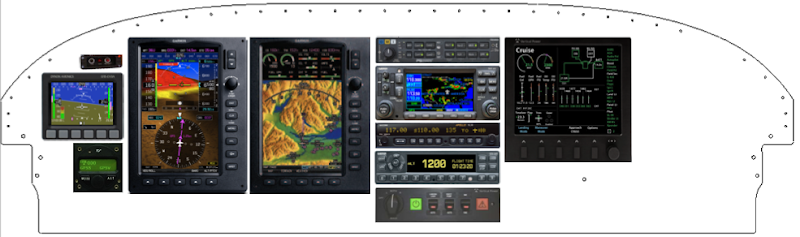
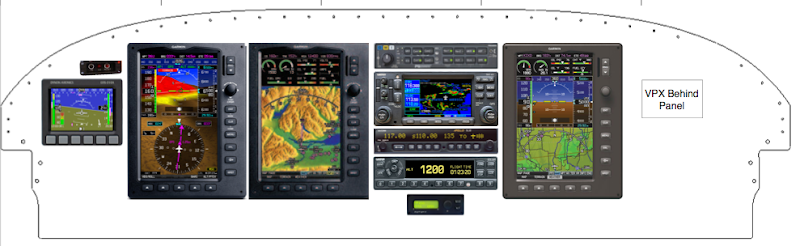
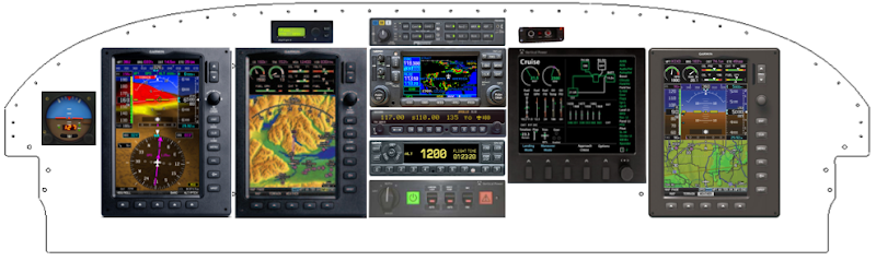
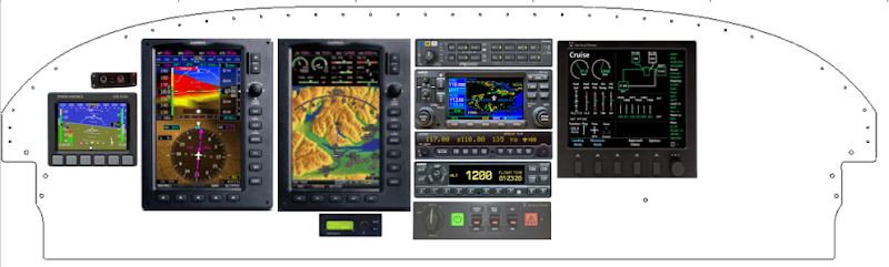
The G3X has arrived, I would be interested in comments on this very first cut of a IFR panel layout for my 7A.

G3X PFD & MFD (Primary attitude)
GX Pilot Autopilot (2nd attitude source)
G430W GPS/NAV/Comm #1
SL30 NAV/Comm #2
GTX330 Transponder with traffic
GMA240 Audio Panel
VP200 Electrical
ADI With GPS & Backup Batt (Backup attitude & track)
Heated pitot (not shown)
CO2 monitor
AFS AOA Pro (not shown)

You can take a look at my layout here:
http://www.dropbox.com/gallery/11894268/2/RV7 Airplane Project/Assembly?h=311f19

I think the VP200 will need to be canted to the left. Is this an issue? Can I get by without the CDI?

Thanks from a long time lurker...
 
Why CDI/GS

I guess my thinking was to have the 430 be able to drive the CDI when/if the g3x fails by a switch flip. Is this overkill? I'm afraid I may be falling on the too much redundancy side. Thoughts?
 
.... Is this overkill? I'm afraid I may be falling on the too much redundancy side. Thoughts?

Yeah. If PFD #1 fails then screen #2 automatically becomes #1. Barring total electrical failure you have two HSIs in those two screens. Having said all this, if you have total electrical failure the VOR head won't work either :).

Of course this is coming from a guy with 5 panel mounted GPSs in his panel....so....you know....maybe I'm not the guy to be preaching two isn't enough :rolleyes:.

Oh yeah, and welcome to the forum!!!!
 
Last edited:
What about SW bug?

What about the case when common sw running on both pfd and mfd brings them both down. This is much more likely then both having simultaneous hw failures right?

Perhaps the thinking is garmin sw more reliable in this aspect?

Can the 430 drive the gx pilot on approach/gs when pfd/mfd locked up and not working? With appropriate hw switch right? Does this involve switching lots of wires with one switch?

Thanks. So much to learn and consider. I appreciate your responses.
 
Hi James,

Welcome to VAF. So how long have you been an engineer, and what kind? :)

cheers,
mcb
 
I guess my thinking was to have the 430 be able to drive the CDI when/if the g3x fails by a switch flip. Is this overkill? I'm afraid I may be falling on the too much redundancy side. Thoughts?

What exactly will you be switching? The inputs to the CDI and EFISes aren't necessarily the same (analog vs. ARINC) and the OBS enters into it as well so it' s not always as simple as just running a few wires through a switch. Don't forget you also have some rudimentary info on the 430 as well as a LOC/VOR display right on the face of the SL-30 display itself.

In the end, if you're terribly concerned about it and want true redundancy, run the SL30 to one system and the 430 to the other, but don't start mixing/matching with switches in the middle. Best solution is to design around the 99th percentile and run both into the 3X. Everything mechanical is prone to failure, including the CDI (and a switch in the middle could render both inop).

Another alternative that is a better use of money all the way around would be to throw out the 3 steam gauges and the CDI altogether, then put in a Dynon D-10 which you CAN easily put feed from the SL-30 along with the G3X simultaneously (and if you want the OBS info to go back/forth then a simple on/on switch between the two). Firstly it's cheaper than buying the CDI and all the steam guages, Secondly you still get an independent backup with a battery backup of it's own. The D-10A also has a host of other good backups too and will run a loooong time on it's internal battery. Lastly it let you slide the radio stack, VP200 screen (which is good to have access to) over to the left, and also probably would allow you to shift everything left a bit by dedicating that space where the CDI is for the Dynon.

BTW, the autopilot source switch is pretty simple, you're only switching three wires and a small switch will work fine.

Just my 2 cents as usual!

Cheers,
Stein

Anyway, lots of ways to skin the cat!
 
Like Stein says - lots of ways to skin that cat! We are using similar equipment to you (no SL-30, no VP unit), and our backup for a G3X software bug is the GX Pilot and the screen on the 430W - in an emergency, it will be plenty sufficient to follow a purple line to a place to land. If the G3X and GX Pilot go up in smoke, we still have the ADI, ASI and Alt - along with the purple line on th 430W. If the 430W dies, we have the two GPS's in the two G3X displays - any way you slice it, we are FAR more redundant than any single engine GA plane in the fleet twenty years ago.

Don't fall prey to the four-failure deep case....it just isn't that realistic - as you know, you only have one engine.....

Paul
 
Last edited:
James,

The G3X / VP-200 integration is nice. The G3X displays the trim and flap position from the VP-200 as well as the mode of flight. And the VP-200 gets all the engine data from the G3X.
 
Panel Version 2

Now that is what I call helpful responses! Thanks.

Doug, thanks for the welcome.

Stein, I like your combo idea. Is this panel version 2 in line with what you meant? I have also started a top level block diagram wiring. Anything look totally out of whack?

http://www.dropbox.com/gallery/11894268/2/RV7 Airplane Project/PanelIdeas?h=c434e6

Paul, do you have a link to your panel?

Marc, thanks for your helpful discussions on the phone in early January.

Matt, I'm an electrical engineer (embedded development ARM / AVR) working in aerospace industry. I'm 33 yrs old and have been working at the same company for 10 years. I've been admiring your panel for a while now and you prolly cost me a few bucks :)

It's nice to have so many well known folks chime in on my first questions posted to VAF.

Love to hear thoughts on initial wiring I posted above...what is missing?
 
Embed image try

11%2010%3A20%3A19%20PM.png


This is done in omnigraffle on the Mac/iPad
Just paste pictures of avionics and set their sizes using manufacturer data sheets. Not elegant but fastest for rough visualization for me.
Panel outline was from vans cad imported and scaled.
 
RV- Panel

I think there is too much clutter on that panel. First if you are going to have an autopilot, airspeed ind, Attitude ind, and Altimeter, looks at the new Gemini series from TruTrak. This one instrument will fulfill all 4 of these instruments. Second if your looking at Vertical power, why not look at the VP-X, get rid of one more screen since everyhitng you really need can display on the G3X. Lastly look at dropping the panel down 3/4 of an inch so you can put everything into a single radio stack. You will find the cleaner the panel, the easier it is to use everything... Just some things to think about... Like someone else said, you are looking at backing everything on your panel up two or three times, but you only have one engine...

Chris
 
Along those same lines, I like Marc and Chris's ideas. If it were me I'd go with the VPX, use the wash in $$'s to buy a 3rd screen. Then put the rectangular GX pilot in the stack (no round instruments in the panel then) :)!

You put some switches under the screens, and for the same $$'s you have a 3 tube panel with a nice central stack and a good independent backup.

Just my 2 cents as usual.

Cheers,
Stein
 
Which one is too cluttered?

Panel mission is IFR...

Chris, are you referring to the one with the three steam gauges down the middle, or the one in post #13?

Stein, I've gone back and forth trying to decide between the VP-X / VP-200. Maybe the G3X - VP-X interfaces will firm up soon and there will be a video demo and I can take a look at them. I haven't seen it yet on the G3X screen. You mentioned you agreed with Marc, but he only mentioned VP-200 in his post. I am a confused. In your post which instrument is the "good independent backup", the dynon I added at your suggestion?

The VP-200 is a good IFR workload reducer. Do you feel the VP-X with a few bypass/backup switches gives enough redundancy when the primary interface for it will be on the G3X. Seems like a lot of eggs in one basket with the G3X being primary attitude & primary electrical control interface?

Do we know yet if only the MFD will get to control the VP-X, or both the MFD and PFD?

I sure am grateful for your comments.
 
Do we know yet if only the MFD will get to control the VP-X, or both the MFD and PFD?

I can't speak specifically to the G3X/VPX interface, but with the other EFIS vendors the VPX has a single serial connection to a single EFIS. I don't know if any of the vendors provides access to other MFDs via their network connection.

I had been planning a VP-200, but economics is now dictating a VP-X. This would be a good question for Marc and your EFIS vendor.
 
G3X - GRT EIS

Does anyone know if info from GRT's EIS can be transfered over to display on the g3x like it can on the GRT EFIS?

I already have a EIS that I bought 8 years ago and just now getting to the instrument panel and really like what the g3x has to offer. Anyone ever done that before?:eek:

Thanks......
 
GJHeck; said:
Does anyone know if info from GRT's EIS can be transfered over to display on the g3x like it can on the GRT EFIS?

I don't think so. The G3X has it's own built-in EIS--just add sensors and it's good to go. There's no provision for it to accept engine data from an external source that I'm aware of. This is a different situation than the interface for VPX/VP-200.
 
Last edited:
Should point out that the panel template from the Van's site depicts the panel as a flat part before the bottom is bent 90 deg. for stiffening, so you actually have about 3/4" less space across the bottom than it appears.
 
Panel,

The first drawing is really what I was refering to having too much stuff, but the second still has just a little too much stuff still, but better, getting there though.

Chris
 
A couple of points of clarification.

The VP-X will work just fine if the G3X or the comm link to the G3X fails. So that should not be a major area of concern. Same with the VP-200. If the display or comm link fails the electronic circuit breakers/trim/flaps will work as expected.

I will post some screen shots of the G3X / VP-X interface soon. Just waiting for some feedback from the Garmin folks. They did a very nice job (as did all our EFIS partners!)

In deciding between the VP-200 and the VP-X, the main difference is that the VP-200 includes some very good pilot workload reduction features, automatic checklists, emergency handing, etc. You can see a table of the differences here.
 
The VP-X will work just fine if the G3X or the comm link to the G3X fails. So that should not be a major area of concern. Same with the VP-200. If the display or comm link fails the electronic circuit breakers/trim/flaps will work as expected.

Marc, please clarify how/if the VP-X system displays data on a 2 screen G3X system if one of the display screens goes out and one remains working...thanks!
 
The VP-X serial connection is wired to the MFD in a 2-screen system.

The VP-X electrical page is shown on the MFD. The trim and flap position and alarm annunciators are shown on the PFD. You can also set the amps gauge to display from a shunt or from the VP-X.

If the MFD fails, then the PFD can't see the electrical page. If the PFD fails, then it goes into reversionary mode and you can see everything on the MFD.
 
Having the third display (PFD) is helpful if you frequently fly with a right seater who actively flies the airplane, but probably not needed if the left seater will do most of the flying. Be careful with your lateral spacing, you need at least 1/2 inch on either side of the radio stack for the radio tray mounting rails. Finally, if you intend to use the flush-mount bracket for the Dynon (recommended, that bezel is pretty tall and looks a lot better flush mounted), be sure to leave space for it. Right now it would be pretty tight for the flush mount bracket, you would need to do a little trimming.
 
Back
Top