What's new
Van's Air Force

Don't miss anything! Register now for full access to the definitive RV support community.

Need help on Sam James Plenum - builders needed!

BillL

Well Known Member
I posted this in the SJ cowl Plenum thread, and got no response, so I will try the direct approach.

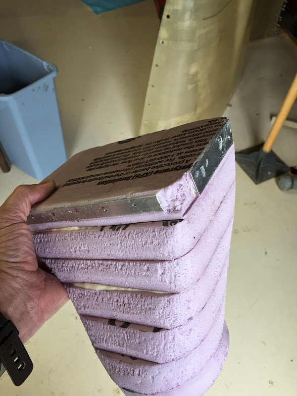
So, I have fitted the cowl with SB fasteners and glassed the inlet rings. SJ builders, please read below and tell me what you would do or did differently. After rebuilding the back flange, I will cut off the front inlets, make some from styrofoam, and re-glass them to fit properly against the forward heads. Also allow for a gradual expansion of inlet air. I really need some experienced opinions here.

Not addressed yet is the fact that 1/3 of the oil cooler is blocked with the rear at this plenum cover level and I have not formulated the details of how to fix that yet.

The baffles have been trial fitted on side and back, but before getting into the fitting at the front of the engine I searched and studied and even cut out the SJ templates. In order to understand the baffles, I got the Lycoming engine installation drawing and used it to overlay the baffles and understand what the exact dimensions are for the Vans baffles.

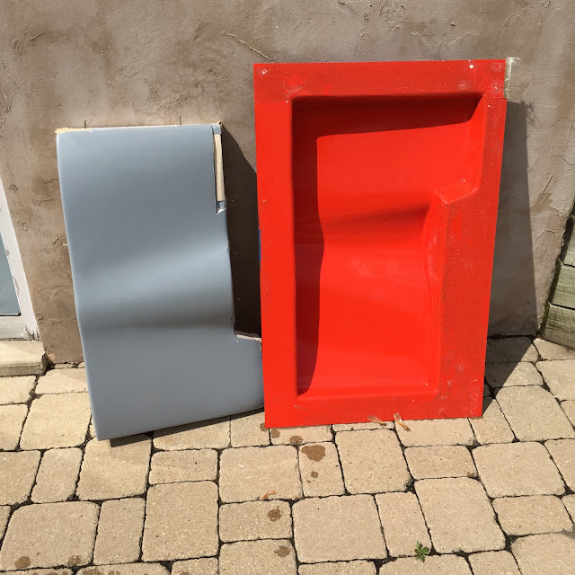
To begin - the SJ plenum is a "universal fit", it does not fit anything. I have an early one, but Sam says the new ones are the same. I am not going to argue with him.

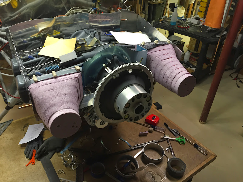
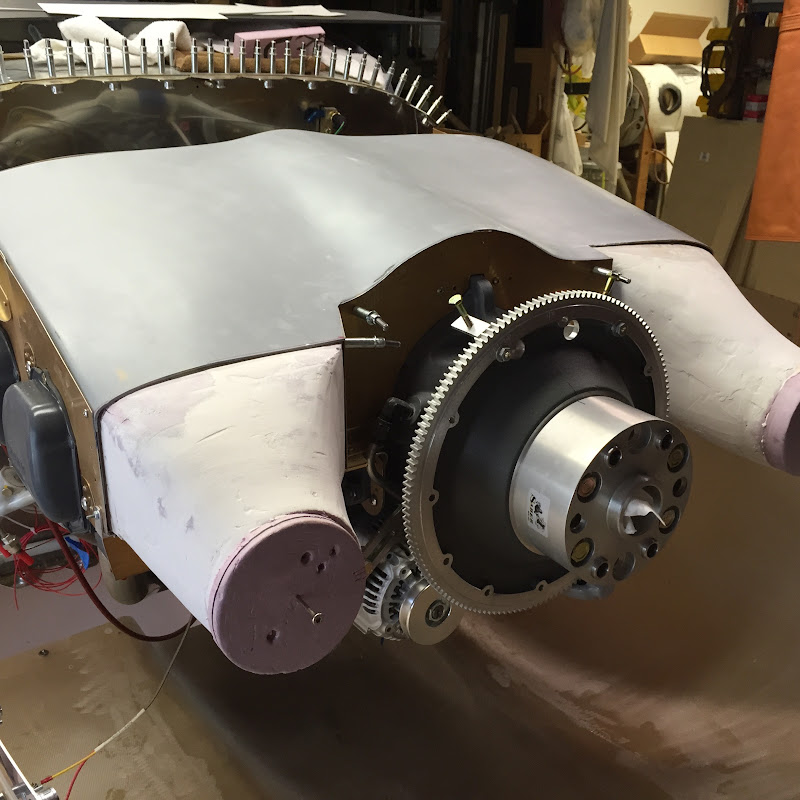
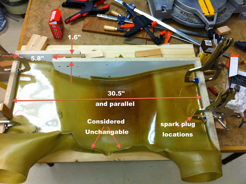
Here is a box built with the exact dimensions expected to fit the engine. It is parallel, spark plug locations provide a good datum for fore/aft locations. Inserted is the SJ plenum. There are a couple of dimensions on the plenum that are good, the side span is perfect and parallel, the forward contour fit to the case is pretty good. The back is bad, are the air inlets are bad. Not shown is that the height above the heads is the same as measured at the center of each head (inline with plug 2" above valve covers).

I used the contour and the plug locations to affix the engine. The contour is tight against the from of the case and down as low as it can go. The inside flow area is 2 inches above the top of the valve covers. Meaning, it can not go lower or I runout of cooler flow area and risk possible air flow throttling at the inlet over the front head/cylinders.

plenum%2520in%2520fixture.jpg


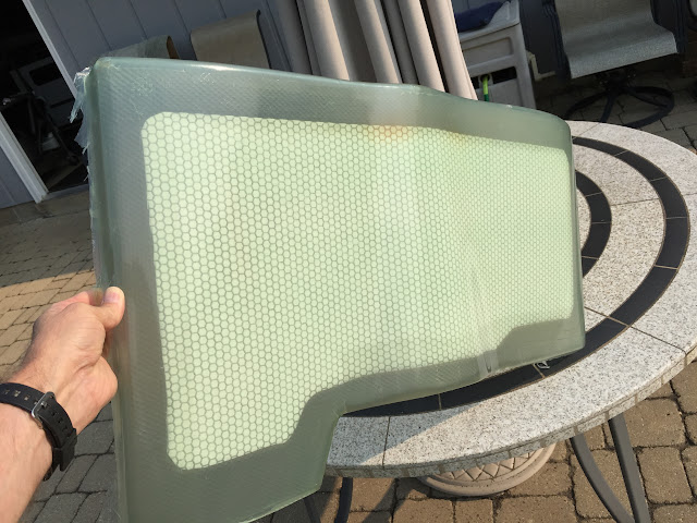
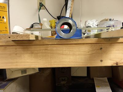
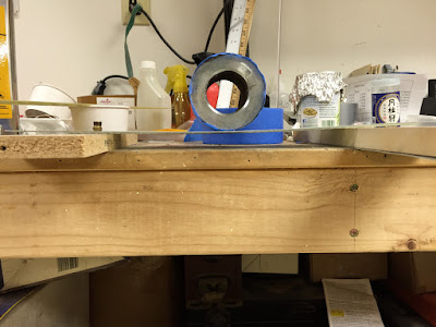
Here is the back - and how the original glass does not follow the baffles. it is off in every way. I will cut off the flange and re-glass that.

plenum%2520back%2520clearance%2520fixture.jpg


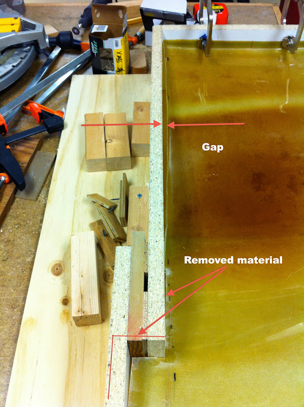
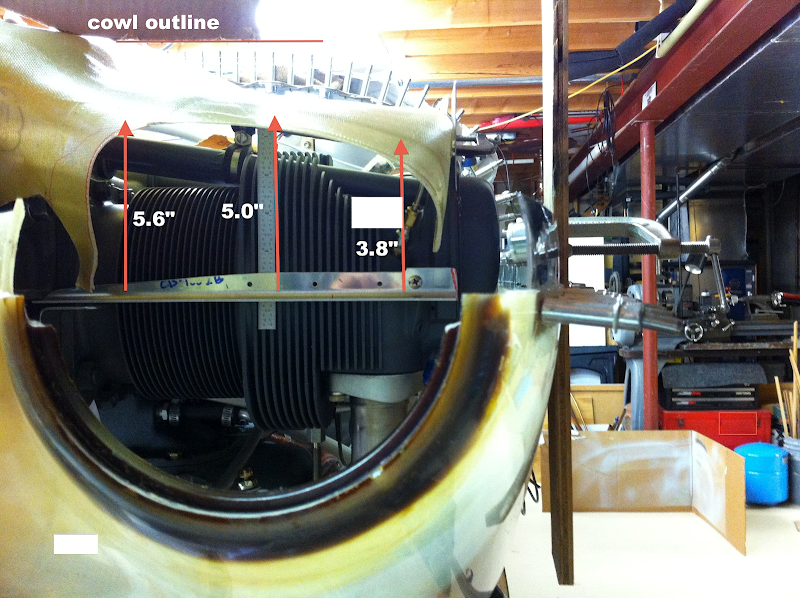
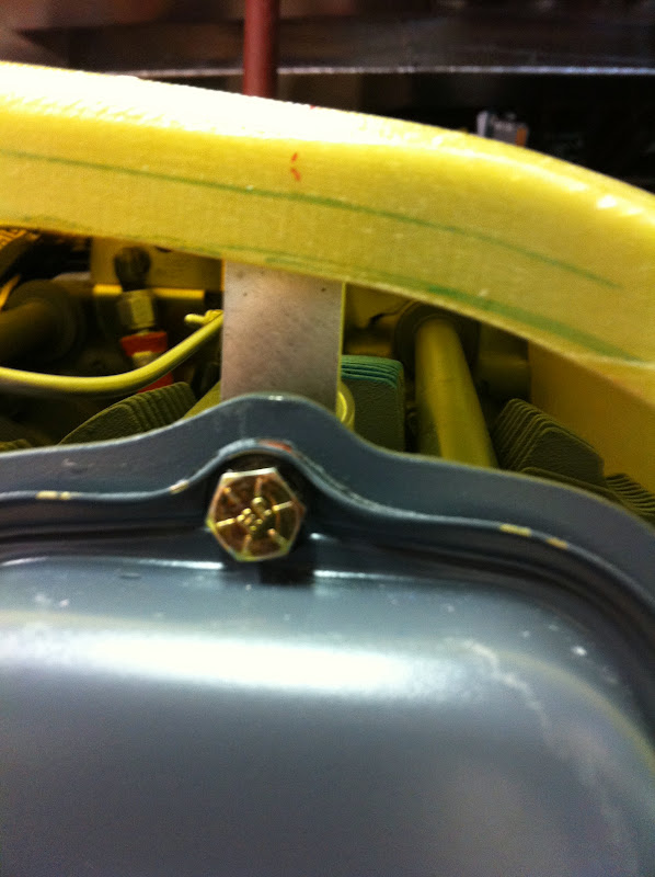
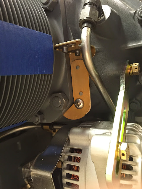
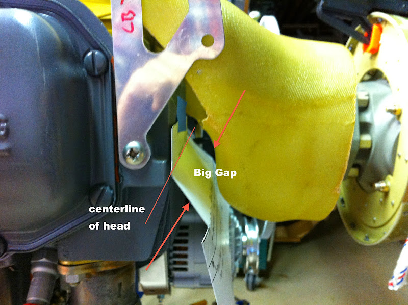
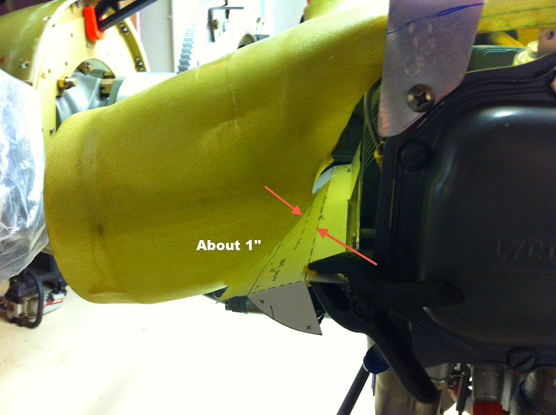
Here is the left and right view of where the inlet snouts "match" to the forward baffles. There is a significant gap on both sides. The left side inlet is centered with the cowl, the right is 1/2" low. it can not be moved anyway with the other constraints.

Right side -

Plenum%2520snout%2520r%253As.JPG


Left:
Plenum%2520snout%2520l%253As.JPG


EDIT - I did look at HydroGuy's, RonDuren, and Mike Bullocks pictures. Rupsters posts had some good pictures too, but he has a 320. All of these contributed immensely to my understanding. I also looked at ALL pictures on the yahoo SJ group. These are just ill fitting parts, and I would suggest making your own.
 
Well if you seen my photos, you know I had to hack my James Plenum up too. I made it work but took many hours doing pretty much just as you are doing. I glassed in the front to fit better and the sides of the inlets to ramp gaps.

For the cooler area I raised it up back there about 1/2-3/4 inch and left the baffles taller back there. I also built a angle mount for the cooler, this makes a small plenum in front of the oil cooler. I find it cools pretty well.
 
Your description of the plenum is similar to mine. I did some variations on the theme. For the oil cooler, I have an angled fitting goes on the back at the left hand side of the rear baffle and the fitting is for a 4 inch scat tube. The tube goes to the oil cooler which is mounted on the firewall lower left. It has been tried before and has advantages that the cooler is not blocked, the cooler is not mounted on the baffles, I could put a butterfly valve to control the air flow to the cooler. If you need more details send me a message.
With respect to the plenum, I rebuilt the back along the entire baffle line. The worst misfit was behind cylinder 4. It all came together well using the baffle as a "form". The front required some addition shaping but everything aligned. Sealing the areas around the front ramp took the greatest thought. I screwed the plenum to the vans ramp which I used with small modifications.
It takes time, but not magic. I guess somewhere the work patience might also appear. In the end, I am quite happy with the product.
 
Update

With all the PM/email responses I have done a couple of things. One was to raise the plenum cover as high as possible. That meant close to the cowling. Actually, the front did not move, but the rear was raised 1 inch. The positioning is done at the spark plug locations. The picture is below. Funny, the earlier post with the "unchangeable" front, got revised. By tilting the back up, the lower ramps of the inlets came nearly exactly inlace to mate to the lower baffle ramps. I will won't use them, as the inlets now are severely pointed down relative to the cowl inlet rings. I used small clay points to determine the clearance and found a couple of things. The plenum cover contour is poorly matched to the cowl. Also this restricts the ability to raise the front and get more flow area to the front heads. Since air has to get past the front to be distributed, then it is a possible "restriction". Are others seeing the same opening? See pict for dimensions.

Note the cardboard template of the cowl profile in the upper left. Sorry for the crummy photo, I need a new camera. Color rendition and contrast on this iPhone are poor.

If the SJ plenum pilots can say that 100kt climb on a hot day (90-100F) yields CHT's in the acceptable range, then it is probably ok. Remember this is a IO360 180hp, no jets, & slick mags.

EDIT: If you look close the 5" dimension is to the left of the ruler. The correct dimension is 3.8" at the right arrow.
Plenum%2520Left%2520Inlet%2520-%2520high-2%2520copy.png


Here is how I positioned the cover. A tab is mounted on a long bolt at each spark plug location. THe back is 3" above the valve cover flat and the front is 2".

Plenum%2520positioner.JPG


Musings:
Negatives:
Smooth finish is on the inside. More work to make it pretty.
The contour is bad limiting the air flow area at the front of the heads.
The back match to the baffles has to be reworked.
Each inlet has to be reworked to make a good transition (good pressure recovery).

I wonder if it wouldn't be easier at this point to custom make a cover using the upper cowl to begin making a mold. That would solve all the above issues except the inlets, and styrofoam bucks are well along for that for either path.
 
Last edited:
plenum

Bill, I will be at Whiteside co. (SQI) at Rockfalls from 7:30 till about 11:00 tomorrow morning (weather permitting- morning fog). I have a James plenum adapted to Vans rectangular inlets. I can take the top cowl off for you to look at if you stop in. Ron 815 291 8864
 
I talked to them and i was told that the plenum fits without any mods. I told them all the problems i was having and was told that i was the first person to report it to them. I told them that many folks have issues. At the end of the day I ended up cutting every flange off and the plenum down the middle. It was alot of work. You can see the work i did if you click on the links in my signature below.
 
James Plenum

Mine was "racked" from corner to corner--had to cut off the rear flange and re glass it, remake the front flange, and realign the inlet areas. It would have been easier for me to have made my own----but this was back in 2005--I assumed that they had fixed these problems!!! It was, however, smooth on the inside! BTW, the cowl fit fine!

Cheers,

db
 
Last edited:
New Direction - - - Progress

Well, with the SJPlenum - - it just was not going to fit well without cutting into many pieces and reassembling. So I decided to make a plenum cover using the inside of the cowl as a mold. (like Paul K)

The air inlet restriction over the #1 and #2 would be eliminated if more of the clearance to the cowl was utilized. I drew up some flow paths ( yes i draw not CAD) and was satisfied that much more flow area was possible and that pressure recovery expansion was possible in the length available.

The inlet ducts will be made separately from the plenum cover. This allows easier installation with screws around the inlet perimeter and removal of the cover (with inlets left in place) for inspection.

Here are some pictures of the pink bucks in place with clearances checked with clay balls on the top.
Air%2520Inlets%2520progress%252001.JPG


I had trouble ensuring the bucks were accurately placed and could be repeatedly installed in the same place, so I glued on some aluminum strips for a hard mount. Now they are quite rigid. Any misalignment with the cowl will me made later in the process.

Inlet%2520buck%2520Aluminum.JPG


The center section was made from cardboard (many interactions) and then formed in .032. I was concerned about the pressure behind that center wall pushing out the baffle bracket into the prop oil line, so a foot was added to prevent movement should that attempt to happen. Better now than to repair later. The perimeter needs to be sanded to match and more clearance made for the tube, but this is it so far.
Baffle%2520right%2520front.JPG


When stacking the pink blocks for gluing (DanH micro method) I found that ensuring the stagger was a pain, so i matched each layer and screwed the layers together with 1 3/4" drywall screws to hold in position to ensure it matched the engine/cowl. Then marked the parts and added glue while still using the screws to keep all in position until set.

More later as progress is made.
 
Keep going Bill. I should have done the same during initial building, but did what I thought was fine at the time. Now I look at mine and want to redo do it for ease of removal. Mine works great and looks ok, but could be better. I keep saying it'll be a winter project to build a new plenum....problem is the winter has been great and I keep flying. Heck I can't even find time to do the Condition Inspection that's due this month.

Good job!

You have that retirement home to finish! I keep this updated to report how it works out, and probably (definitely) ask for help along the way.
 
One more plenum

Reading the above, it looks like a universal story. For the plenum,I had changes on the back, some on the sides and creative glassing on the front. The bottom line is that it fits very well now and I think the effort is worth it. I just started flying and the CHTs are just below 400F at 2600rpm/26"MP. At more traditional cruise numbers, say 24/24, the CHTs are at 350F. This is for an engine with two hours.
For the oil cooler, I moved it away from the baffling and put it on the firewall with a 4" scat tubing connected to the plenum behind cylinder 4. The oil temps are good - about 170-174F for 2400/24.
I can provide some photos when I get home if you would like and walk you through it. With patience, glassing is a creative art as long as it is done with lots of disposable gloves. BTW, use some of Vans sheet metal near the cylinders and it will say a lot of work.
 
Thanks , Jay

I am using the Vans baffle kit all around. I have yet to finalize where the two air inlets will terminate and specific fastener selection/spacing. It appears that the inlets can fasten directly to the angle across the front of each head and in the same plane up the outsides. The right side can easily have all fasteners in the same plane. The center sections were too large to make from existing metal, so I made them from extra .032" I had purchased in advance. The plane of the left inlet is offset by 2+" to the rear according to cylinder offset. Locations of fasteners and transition to the cover is not finalized for the left side.

The plenum cover is intended to be molded using the inside of the top cowling. Walls will be made to facilitate forming a lip on the cover. The walls will match the dimensions of the baffles to allow the lips to fit within the aluminum perimeter. The attachment to the two inlets will be a lap joint. The tops of the baffles are now cut to a 1/2" clearance from the cowl. I am planning on maintaining 1/2" clearance in the final fitting. It seems the outside front corners of the engine are the most likely to hit, but the angle of rotation also gives additional clearance margin there.

edit: One reason for the custom cover is I wanted to mount the oil cooler in the standard location. I have enough customer stuff to work on already and I think with the increased flow area (over the SJ plenum) the oil temps will be fine as I have no piston cooling jets.

Hopefully, this is an adequate visual description of the plan. There are potential issues with separation, but these are not an issue at this time.

Suggestions are welcome.
 
Last edited:
Photos

Bill,
Here are some of the photos of the installation. No installation is uniquely good (although each of us would like to think so). I used the maximum amount of Metal baffle parts and almost all worked. Note the oil cooler. Parts came from Van's. It is heavier perhaps, but reduces stress on the baffles and the need for a large area behind cal #4. The white areas on the plenum photos are my creation to create a seal. I did leave the lifting bracket and there was plenty of room - IO360M1B
http://i1378.photobucket.com/albums/ah110/jaypearlman/DSC_4295_DxO2a_zpsw3gfdprc.jpg
http://i1378.photobucket.com/albums/ah110/jaypearlman/DSC_4305_DxO2a_zpsphsksfvv.jpg
http://i1378.photobucket.com/albums/ah110/jaypearlman/DSC_4304_DxO2a_zpswokdn80s.jpg
http://i1378.photobucket.com/albums/ah110/jaypearlman/DSC_4301_DxO2a_zps1tv6uhzx.jpg
http://i1378.photobucket.com/albums/ah110/jaypearlman/DSC_4299_DxO2a_zps5ghcwyng.jpg
 
Update

First a thanks to Brian Alley of CarbonfiberComposites in West Virginia. Brain took my cold call, talked to me for hours and reviewed my setup and failures. He freely shared valuable information of how do to this, something I could not find anywhere else.

I made a first try plenum cover by using the inside of the upper cowl. I did not account for the engine offset and it did not fit very well. So, lots of cutting patching and the frankenstein version was competed to fit in all directions and have a pleasing contour. Rather than keep this one as a usable part, I decided to make a mold and have a go at vacuum resin infusion process.

Here is the original article with modified inlets. It fits the stock baffles on three sides nicely. There is a recess for the overlaps between the heads and in the back left corner.

IMG_1332.jpg


Proceeded to make a mold and the result:
IMG_1330.jpg


Fast forward through the trials and failures of resin infusion (+money and shipping delays) - let's be nice and call it "development". We arrive at the third piece.
IMG_1386.JPG


Each piece had a list of lessons learned and elements needing adjustment. One was flexibility. 5 Layers of 8.9 oz glass seemed too flexible. Here are two pictures comparing stiffness of a 5 layer sample to a 2 glass-core-2 glass sample. The left picture is hitting the bench!
IMG_1381.jpg
IMG_1380.jpg


The plenum cover from the mold takes all of 5 min to fit to the baffles. Also, there are no pinholes and the finish is ready to stuff, prime and paint. Further updates will be provided with finished inlets - later. I think the whole plenum fitting job could be cut to 1 hour with well fitting parts. From unboxing to completed with fasteners.
 
Last edited:
Back
Top