What's new
Van's Air Force

Don't miss anything! Register now for full access to the definitive RV support community.

Alternator Ring Terminal Breakage

mike

Member
Just a note for those in the final stages...

Sunday I went out to go fly the -9A. I taxied out to 35 and everything was beautiful. Clear skies everywhere. I was going to run up to Sherman for some gas.

But just as I pulled back power after my run up I noticed my amps go negative and my voltage go to 11.7v. Oh no, either I just lost a belt or the alternator just went out. Well, I'm not going to fly with something like that going on, so I taxied back to the hangar. When I pulled the cowl I the belt was intact and there was no sign of damage to the alternator. So I pulled the bottom cowl as well.

I started wiggling things to find out if there were any loose connections. When I grabbed the connector that goes to the alternator , something felt funny inside the rubber boot. So I pulled off the boot and... the ring terminal had broken off inside of the boot.

img_4361.jpg


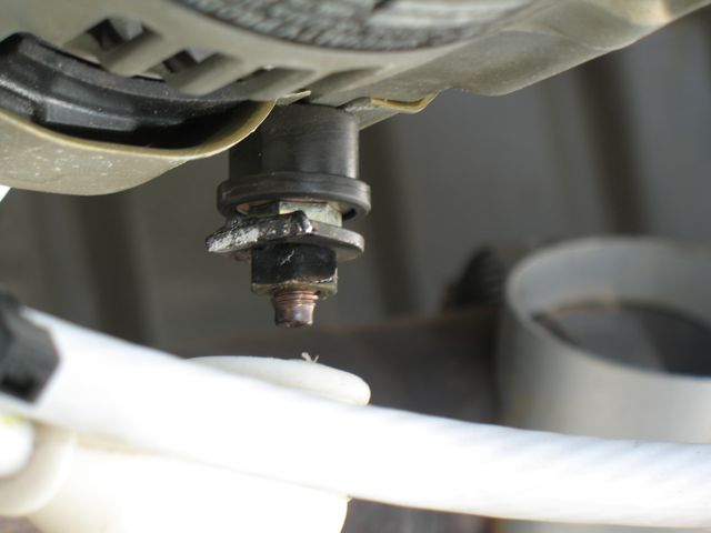
So no flying until I can place an order to B&C for a new ring terminal for 6awg wire.

Now I'm considering adding an additional brace for the rather thick alternator wire.

Regards,
Mike Schipper
 
Mike, that is a common failure if the leads to the terminal are not supported close to the alternator. Doing so should keep that from happening again.

Martin Sutter
building and flying RV's since 1988
 
One other thing you might want to check are the mount brackets for the alternator itself; I had an identical failure with the Van's 60a unit... while poking around under there with a flashlight I noticed the aft stamped steel mount was cracked through. Methinks that this broken mount set up a vibration that cracked the ring terminal. A new ring terminal bolted to a new AutoZone alternator had me back in bidness, quick and cheap.
 
Just about the same thing...

...happened to my Tiger over Roswell, NM last summer, but it was the field terminal, and was a two year old replacement mil-spec terminal.

I'd like to blame the aliens in that area, but it was a lack of wire support - but per the factory parts manual...:rolleyes:

Some aircraft (not my Tiger though...:(...) manage to use an Adel clamp on on the aft end of the alternator case through bolts to support the wires.

If this works out with your wire rounting, it might be a good fix.
 
Burndy Terminals are the answer

Just spotted this thread while searching for something else. The problem with the Amp ring terminals commonly used, is that they are made from copper flat stock. The terminal is then rolled and the split joint soldered together.

Burndy terminals are made from copper tubing, so there is no seam and no weak spot. Better still, the flat area where you bolt the terminal up to your starter, solenoid, etc is double thickness. To make that area, they smash the tubing flat. Best of all, you can get them with a second crimp support. Bob N touts the PIDG terminals as superior due to this feature. See attached photo of a Burndy ring terminal installed on a 2 AWG wire.

Burndy-Ring-Terminal-1.jpg
[/url][/IMG]

Burndy-Ring-Terminal-2.jpg
[/url][/IMG]

Burndy-Ring-Terminal-3.jpg
[/url][/IMG]


Burndy terminals are industrial products, used by commercial electricians. I bought mine at my local Graybar supply house. I learned about these from an IT guy who used to be an avionics tech.

https://hubbell.dcatalog.com/r/BURNDY-Full-Line-Catalog/?page=1

Charlie
 
I suggest using welding cable for alternator and starter runs would also mitigate the problem. Not nearly as rigid so terminal fatigue failure is reduced.

I did the torch fire test on welding cable and standard Tefzel cable. The welding cable did better.

Carl
 
Good tip, Carl. To clarify, the photos above show a master contactor terminal, which ended up as scrap. Regardless of cable used, these terminals are stronger.
 
Last edited:
...Burndy terminals are industrial products, used by commercial electricians. I bought mine at my local Graybar supply house. I learned about these from an IT guy who used to be an avionics tech.

https://hubbell.dcatalog.com/r/BURNDY-Full-Line-Catalog/?page=1

Good tip, Carl. To clarify, the photos above show a master contactor terminal, which ended up as scrap. Regardless of cable used, these terminals are stronger.

The terminal in the image above (YA25-L) is on page C-23 of the linked-to catalog.
 
Burndy part number

Mike,
Going through my receipts, I found the following Burndy part number for a 6 AWG ring terminal with extra long barrel [for double crimping onto the insulation]

YA6C-LBOX
 
Improved flexibility

For those wanting to go the Tefzel like material (ETFE) and tin coated copper for protection against corrosion and oxidation there is a product out that uses more strands of finer wire to improve flexibility. As an example, typical mil spec Tefzel uses 133 strands of 29 awg (8 awg) whereas this more flexible material uses 665 strands of 36 awg also 8 awg. It is more expensive but if limited to wire that connects to the engine, alternator or starter reasonable. It is considerably more flexible (than standard Tefzel) and since I've never used welding wire cannot compare.

https://www.digikey.com/en/products...ospace-defense-and-marine/82A0111-8-9/8604802
 
The Burndy commercial crimp connectors are indeed much stronger than the typical aircraft types, such as also THOMAS & BETTS, and the way to go. There are many manufacturers of these and IMO are vastly preferable to use on all our fat cable ends at battery, solenoids, alternator, starter, etc. They are categorized by cable size, one or 2 holes, lug hole size, and barrel length - short, normal, or long, and are typically available in many combinations of these parameters. Normal and short work fine. I usually put two layers of heat shrink over the crimped barrel section. One common place anyone can find them is Grainger, where you simply select all of your parameters and they pop up the available parts, usually about $2+ each. Your search term is "One-Hole Compression Lugs"

As others have noted, the other common vibration induced breakage is the field connection at the alternator. The B&C alternator field connection actually has two common field terminals and one thing to do is to connect to both of them separately to a junction point of the field wire a few inches back from the alternator. in addition, use finer high strand count highly flexible silicone insulated wire for that last section of the field wire into the field connector and support with a slight loop and no tension on the wire.
 
Looks like a well designed connector.

Just spotted this thread while searching for something else. The problem with the Amp ring terminals commonly used, is that they are made from copper flat stock. The terminal is then rolled and the split joint soldered together.

Burndy terminals are made from copper tubing, so there is no seam and no weak spot. Better still, the flat area where you bolt the terminal up to your starter, solenoid, etc is double thickness. To make that area, they smash the tubing flat. Best of all, you can get them with a second crimp support. Bob N touts the PIDG terminals as superior due to this feature. See attached photo of a Burndy ring terminal installed on a 2 AWG wire.

Burndy-Ring-Terminal-1.jpg
[/url][/IMG]

Burndy-Ring-Terminal-2.jpg
[/url][/IMG]

Burndy-Ring-Terminal-3.jpg
[/url][/IMG]


Burndy terminals are industrial products, used by commercial electricians. I bought mine at my local Graybar supply house. I learned about these from an IT guy who used to be an avionics tech.

https://hubbell.dcatalog.com/r/BURNDY-Full-Line-Catalog/?page=1

Charlie

Any downside of crimping the insulation inside the barrel? (Assuming 50% was stripped of insulation under the barrel). It appears to insert Tefzel under the barrel one size increase to allow for insulation clearance will be needed. Looks like a nice connector!!
 
Any downside of crimping the insulation inside the barrel? (Assuming 50% was stripped of insulation under the barrel). It appears to insert Tefzel under the barrel one size increase to allow for insulation clearance will be needed. Looks like a nice connector!!

These lugs are designed to fit the wire gauge exactly/fairly tight for proper crimping. In fact, you typically need to be careful when flush cutting the end of the cable and stripping the insulation to keep all the wire strands aligned and retaining the slight twist, and having the end nice and circular to fit into the lug without strands getting crumpled or left out.

I would not recommend going over size and including the insulation. Strip just right for the insulation to butt the lug, and cover crimped section and a portion of insulation with heat shrink tubing.
 
And so the ?

These lugs are designed to fit the wire gauge exactly/fairly tight for proper crimping. In fact, you typically need to be careful when flush cutting the end of the cable and stripping the insulation to keep all the wire strands aligned and retaining the slight twist, and having the end nice and circular to fit into the lug without strands getting crumpled or left out.

I would not recommend going over size and including the insulation. Strip just right for the insulation to butt the lug, and cover crimped section and a portion of insulation with heat shrink tubing.

Picture shows 2 awg with insulation (I think) being inserted into a 1/0 awg. connector. OK or not OK?
 
Any downside of crimping the insulation inside the barrel? (Assuming 50% was stripped of insulation under the barrel). It appears to insert Tefzel under the barrel one size increase to allow for insulation clearance will be needed. Looks like a nice connector!!

Crimping the insulation works to prevent a fatigue failure just aft of the terminal. See linked article below:

http://www.aeroelectric.com/Reference_Docs//Seminar_PP_Slides/09_Terminals_and_Connectors.pdf

You are correct. I used a terminal for 1/0 AWG wire. To accommodate the smaller 2 AWG wire, I filled the main [bare wire] crimp area with loose copper wire strands to fill it up. As Carl mentioned earlier, best to use 3M "triple thickness" heat shrink tubing to help support the wire.

Ground-cable-to-fuselage-terminal-2.jpg
[/url][/IMG]

Ground-cable-to-fuselage-terminal-3.jpg
[/url][/IMG]
 
The AeroLectrics reference is not pertinent to commercial compression lugs. Here are two sets of instructions for crimping compression lugs, and a key aspect of proper crimping is for the lug size to match the wire size. Over size and insulation inclusion is not a good idea.

https://hubbellcdn.com/ohwassets/HCE/burndy/compression-terminals/compression.pdf

https://media.ilsco.com/document/public/Connector-Installation-Guide.pdf

The insulation butts to the lug. And as previously discussed, you can pretty it up with heat shrink tubing. For these size wires, the vibration stress at the lug should be managed with proper support of the cable somewhere near the termination, for example at a starter, an adel clamp at one of the starter mounting bolts.
 
Back
Top