
Van's Air Force
You are using an out of date browser. It may not display this or other websites correctly.
You should upgrade or use an alternative browser.
You should upgrade or use an alternative browser.
Critique my ELT mounting
- Thread starter Blain
- Start date


Canadian_JOY
Well Known Member
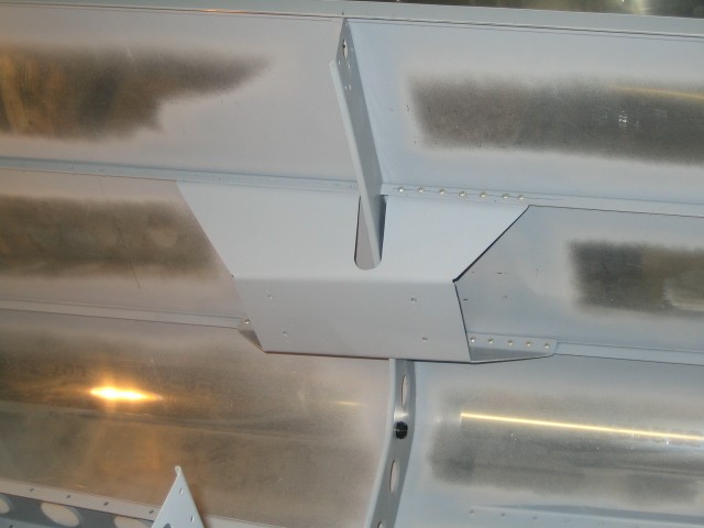
From the photos it's hard to tell how far aft of the bulkhead the ELT is mounted. Since your antenna location isn't stated it's hard to know where the coax cable will be routed. One wants to ensure the cable can be routed and connected to the ELT without an excessively tight bend radius and that the cable, once in place, won't chafe against the aft baggage bulkhead cover or similar hard surfaces. Ditto for the control cable.
The mount looks plenty stout. It could be stiffened even further by adding some stiffeners, in the form of 90 degree angles bent from sheet stock and riveted in a vertical orientation to the arm of the mount which projects downward on an angle to the lower attachment point. Stiffening this arm will reduce flexing of the mount.
The mount looks plenty stout. It could be stiffened even further by adding some stiffeners, in the form of 90 degree angles bent from sheet stock and riveted in a vertical orientation to the arm of the mount which projects downward on an angle to the lower attachment point. Stiffening this arm will reduce flexing of the mount.
The older I get the more I realize that nothing can be easily be accessed through the aft baggage compartment.  In your proposed location, in the event of an off-airport landing, you would not have easy access to the ELT. One would have to crawl in back with a screwdriver and remove the bulkhead panel to arm or remove the ELT. If injured this could be challenging.
I would move the ELT 12 inches forward and place it in front of the bulkhead panel, on the top right hand side of the baggage hat shelf. Cable routing would be identical. You would eliminate the weight of the mounting bracket, provide easier access, and allow for a visual inspection.
My 2 cents,
MD
In your proposed location, in the event of an off-airport landing, you would not have easy access to the ELT. One would have to crawl in back with a screwdriver and remove the bulkhead panel to arm or remove the ELT. If injured this could be challenging.I would move the ELT 12 inches forward and place it in front of the bulkhead panel, on the top right hand side of the baggage hat shelf. Cable routing would be identical. You would eliminate the weight of the mounting bracket, provide easier access, and allow for a visual inspection.
My 2 cents,
MD
Last edited:
Blain
Well Known Member
From the photos it's hard to tell how far aft of the bulkhead the ELT is mounted. Since your antenna location isn't stated it's hard to know where the coax cable will be routed. One wants to ensure the cable can be routed and connected to the ELT without an excessively tight bend radius and that the cable, once in place, won't chafe against the aft baggage bulkhead cover or similar hard surfaces. Ditto for the control cable.
The mount looks plenty stout. It could be stiffened even further by adding some stiffeners, in the form of 90 degree angles bent from sheet stock and riveted in a vertical orientation to the arm of the mount which projects downward on an angle to the lower attachment point. Stiffening this arm will reduce flexing of the mount.
Going to shift it aft enough for cable bend
.064" seems rigid enough.
Are you planning on cutting lightening holes?
Yes. Mostly because they look cool..
My thought was to use thumbscrews to attach the bulkhead panel. I thought this location would be an improvement over the battery area that seems to be popular.The older I get the more I realize that nothing can be easily be accessed through the aft baggage compartment.
I would move the ELT 12 inches forward and place it in front of the bulkhead panel, on the top right hand side of the baggage hat shelf. Cable routing would be identical. You would eliminate the weight of the mounting bracket, provide easier access, and allow for a visual inspection.
MD
The baggage shelf isn't strong enough without additional bracing. Wouldn't there be a concern with items stored in the baggage compartment contacting the ELT?
+1 on the lightening holes.
How about the thickness of the material? Maybe .032" 2024-T3 with flanged holes. Every ounce counts!
Try bending it from a single sheet. . . you already have a great template.
Tried bending the .064" with a large radius. Split at bend. Gave up and went to angle stock.
Got'cha, Mel. Going with the right arm rest area for antenna. Will need to pass through that bulkhead. My understanding is the possibility of cutting the cable on impact. What about running it through an additional tubular sheath where is passes through the bulkhead?When running your ELT antenna cable, do NOT run it through bulkheads. Run it around them.
In the event of a crash if the cable is running through bulkheads, the bulkhead may be distorted and cut the cable.
Tried bending the .064" with a large radius. Split at bend. Gave up and went to angle stock.
Bending thicker aluminum, you almost always have to bend perpendicular to the grain. Sounds like you might have tried bending with the grain.
91.207(b): Each emergency locator transmitter required by paragraph (a) of this section must be attached to the airplane in such a manner that the probability of damage to the transmitter in the event of crash impact is minimized. Fixed and deployable automatic type transmitters must be attached to the airplane as far aft as practicable.
Note: The reg says practicable not possible.
I have mine under the vertical stab in the open space between the left and right horizontals. As for ease of access, remove the fiberglass fairing for mx or in an actual emergency, break the fairing to gain access if time is critical. Antenna is mounted just forward of the vertical stab, 18" cable run. My understanding is that aircraft tail areas often survive more intact than cockpit areas. Dan from Reno
JonJay
Well Known Member
If you wish to meet the reg's, you follow the manufacturers recommendations....
Here is one popular manufacturers mounting instructions;
"The ELT shall be mounted to primary load-carrying structures such as trusses, bulkheads, longerons, spars, or floor beams. (not aircraft skin) The mounts shall have a maximum static local deflection no greater than 2.5mm (0.1 inch) when a force of 450 newton's (100lbs.) is applied to the mount in the most flexible direction. Deflection measurements shall be made with reference to another part of the airframe not less than 0.3 meter (1 foot) nor
more than 1.0 meter (3 feet) from the mounting location."
Will your mount meet the above? If it does, you are good to go.
I would be surprised, mounted off of the longeron that distance, if it met the deflection requirements using a flat sheet, even .063.
Last edited:
Critique my ELT mounting
It is way heavier than it needs to be, but because it is a shelf, it might have a risk of buckling under crash G's if you didn't make it that heavy (even them it still might be).
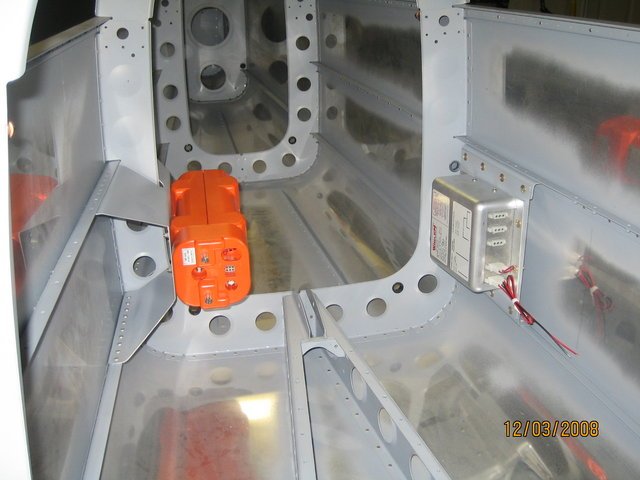
Something like THIS would be more than adaquate. It is not for an RV-8 but you could custom make one using the same concept.
When installed it looks very similar to the bracket that the strobe power supply is mounted too in the second photo of THIS POST. I think that builder should have done the same on the right side for mounting their ELT.
This type of bracket is very strong because it has very short flanges (very low bending moments). This allows it to be made of relatively light material, keeping the weight to a minimum.
Last edited:
Blain
Well Known Member
91.207(b): Each emergency locator transmitter required by paragraph (a) of this section must be attached to the airplane in such a manner that the probability of damage to the transmitter in the event of crash impact is minimized. Fixed and deployable automatic type transmitters must be attached to the airplane as far aft as practicable.
Note: The reg says practicable not possible.
I have mine under the vertical stab in the open space between the left and right horizontals. As for ease of access, remove the fiberglass fairing for mx or in an actual emergency, break the fairing to gain access if time is critical. Antenna is mounted just forward of the vertical stab, 18" cable run. My understanding is that aircraft tail areas often survive more intact than cockpit areas. Dan from Reno
Isn't that contrary to keeping weight off the tail? Seems like a CG problem.
I have mine straddling the bulkhead so it's not too far aft to reach. There is a swing open access door on the baggage compartment shelf to access the switch if necessary.
I was going with a mount like yours but was concerned about the vertical orientation of the saddle. Seems like the most common stress is hard landings which induces the load on the straps and clasps.
Blain
Well Known Member
Yup. I know better. Got excited and didn't check the grain.Bending thicker aluminum, you almost always have to bend perpendicular to the grain. Sounds like you might have tried bending with the grain.
I was going with a mount like yours but was concerned about the vertical orientation of the saddle. Seems like the most common stress is hard landings which induces the load on the straps and clasps.
There is no mounting requirement that the mounting bracket has to be underneath the ELT.
There are 1000's of them installed that way. In certified and experimentals.


WA85
Well Known Member
Limit Load Factors
It is well understood that the Vans aircraft are not an FAA certificated aircraft and do not have to meet FAA certification requirements, however;
when installing the ELT in my RV-8, I wanted to ensure that it, and the mounting structure, would reasonably survive at least 9.0 g crash load impacts. Recommend reviewing FAA AC 43.13-2B table 1-1, which lists the FAA's minimum limit load factors for mounting items to the airframe. It mimics the ELT installation requirements for a load analysis of the ELT mount by evaluating the bending of the mount with applied loads. It also has good information on how to meet the load limit requirements. I used the aerobatic limit load factors of 1.5 g sideward, 4.5 g upward, 9.0 g downward and forward. Its it pretty simple, take the mass of the item to be mounted, multiply by the g load factor and then apply that load to the structure using a pull gage or other means. From the picture of the proposed shelf type mount, it does not look like it may buckle under the 9.0 g downward and forward limit load factor, especially using 3/32nds rivets.
The FAA limit load factors are a good practice to follow when (if possible) whenever making an alteration or mounting items of mass to "any" airframe.
Bubblehead
Well Known Member
That sure seems to eat up a bunch of useful baggage space. Seems like there has to be a better way. I still have the old style unit and it is pretty slim and even mounted low it sometimes gets in the way of putting a bag back there.
Remember that when you put stuff back there you are reaching over the rail, around the canopy, and holding the seat back forward. It is not fun trying to jockey a bag that ways 10 or 15 pounds at arms length one handed to get it past an ELT.
Remember that when you put stuff back there you are reaching over the rail, around the canopy, and holding the seat back forward. It is not fun trying to jockey a bag that ways 10 or 15 pounds at arms length one handed to get it past an ELT.
Sam Buchanan
been here awhile
My thought was to use thumbscrews to attach the bulkhead panel.
Pretty sure the bulkhead is a structural part of the RV-4 airframe. It needs to be secured with structural fasteners.
Last edited:
Blain
Well Known Member
It's behind the last baggage bulkhead. Your point about the difficulty accessing this area under the best of circumstances does make one consider the difficulty of accessing after bending the plane and possibly limiting injuries.That sure seems to eat up a bunch of useful baggage space. Seems like there has to be a better way. I still have the old style unit and it is pretty slim and even mounted low it sometimes gets in the way of putting a bag back there.
Remember that when you put stuff back there you are reaching over the rail, around the canopy, and holding the seat back forward. It is not fun trying to jockey a bag that ways 10 or 15 pounds at arms length one handed to get it past an ELT.
That's it, it gets mounted on the glare shield!
Probably the same in the -8. 5 each #8 stainless steel screws with a flag head should serve the strength requirements. Seems like they preform as shear and not tensile in this panel.Pretty sure the bulkhead is a structural part of the RV-4 airframe. It needs to be secured with structural fasteners.
I appreciate all the input I've received vetting the design.
ELT Antenna base BNC install
Another ELT question I have concerns the bulkhead BNC fitting I am using to mount my antenna on. Should it be in direct contact with aircraft structure aluminum, or should the bulkhead fitting have non metallic washers to insulate it from the structure? I was thinking it should be in direct contact to give the antenna a 'base plate' for better transmission, but the BNC bulkhead fitting came with a rubber washer so it made me think.
Another ELT question I have concerns the bulkhead BNC fitting I am using to mount my antenna on. Should it be in direct contact with aircraft structure aluminum, or should the bulkhead fitting have non metallic washers to insulate it from the structure? I was thinking it should be in direct contact to give the antenna a 'base plate' for better transmission, but the BNC bulkhead fitting came with a rubber washer so it made me think.
Another ELT question I have concerns the bulkhead BNC fitting I am using to mount my antenna on. Should it be in direct contact with aircraft structure aluminum, or should the bulkhead fitting have non metallic washers to insulate it from the structure? I was thinking it should be in direct contact to give the antenna a 'base plate' for better transmission, but the BNC bulkhead fitting came with a rubber washer so it made me think.
These antennas depend on a ground plane for proper operation. There may be a rubber washer to keep water out, but there must be an electrical path from the coax braid to the aluminum skin. Just one side would be okay.
Bubblehead
Well Known Member
It's behind the last baggage bulkhead. Your point about the difficulty accessing this area under the best of circumstances does make one consider the difficulty of accessing after bending the plane and possibly limiting injuries.
I just took another look at the pictures and you are right. It is under the baggage floor. Is access to the ELT required?
David-aviator
Well Known Member
FWIT my ELT is mounted to floor just outboard of my right knee. I can reach it with shoulder harness unhooked.
I just took another look at the pictures and you are right. It is under the baggage floor. Is access to the ELT required?
All new ELTs have a cockpit mounted remote off-on-arm switch. The reasons you would want easy access after a crash might be:
You are leaving the site and want to take the ELT with you, along with a portable antenna of some sort;
The antenna or coax was damaged in the crash (maybe the antenna is upside down) and you want to attempt a repair.
I cannot think of other reasons, other than access for normal maintenance under normal circumstances.


Given that a large proportion of ELTs fail to activate in a crash (I've heard as high as 85%, but don't have the data), ISTM that the best mount is the lightest. Any crash bad enough, say, to bend bulkheads severely enough to sever coax cable will almost certainly destroy the antenna.

