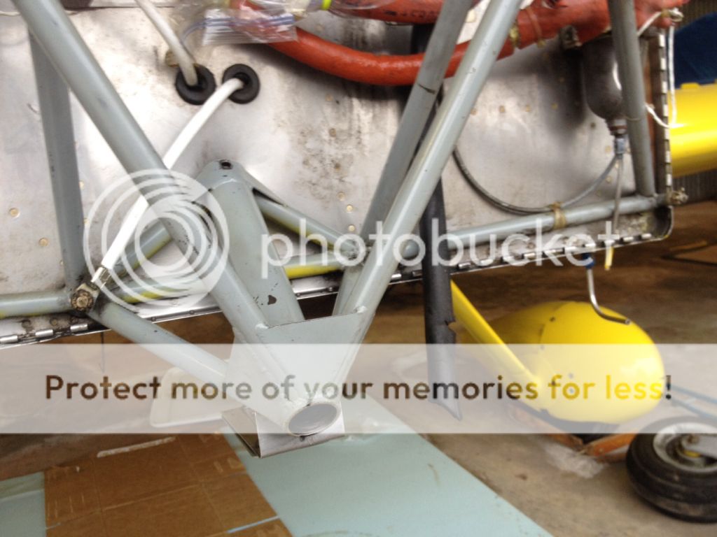
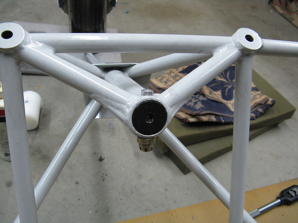
When the nose gear fork is deflected, the normal force at the tire contact patch is offset a significant distance (10 inches?) from the center plane, creating a twisting moment about the axis of the gear leg socket and generating high shear loads on the bolt, even if the fork isn't against the stop.
Roger
I agree (though because of the pivot angle stops, I think the offset is more on the order of 6" at max deflection, but I have never measured it) .
I was speaking in the context of normal operation and an acceptable level of load... I.E. not adding
extra side (torsion) load on the nose gear leg than is normally experienced by A model RV's .
We all know that there is some level of load induced on the leg; otherwise all that would be needed to hold it in place would be an allen set screw.
As has been mentioned countless times here in the forum (by many, not just me), do not loose sight of the big picture.
There are thousands of A model RV's flying with this style of nose gear attachment. Of those, I am only aware of 2 bolt failures that occurred during seemingly benign ground operations. That small a number... in thousands currently operating, indicates (to me at least) something specific about those two airplanes.
I have not crunched any numbers, but to me it is doubtful that in these two instances, the bolt failed as a result of a single load event, or even multiple events of the normal expected loads (see my comment above about thousands of "A" models flying).
I would be very interested in seeing close up high res. photos of the bolt ends.
I am pretty confident that it would show evidence of progressive fatigue failure through a major portion of the cross section, with the final flank turn finishing it off.
There is a lot of different issues that could induce a fatigue failure, but a couple of prominent ones would be a loose fit of the bolt in the bore, and nose wheel shimmy. Add those two together on a single airplane and it would be that much worse. Throw flank turns into the mix on regular basis and it is worse still. Then there is still the possibility of an incorrectly installed fork pivot stop bracket. Hopefully everyone here knows that the "T" portion of the bracket is supposed to be pointing fwd. It would be interesting to here how many people check and find theirs pointing aft.
I hope I don't sound like I am downplaying the event. It is sad to see any RV get damaged, and have the owner have to deal with the cost and trouble of repairs. Just pointing out that 2 out of 2000+ (<.1%) is a very small #, that is likely preventable by just making sure the standard AN bolt is a tight fit when installed. Then doing regular inspections to make sure it is staying that way.
Any amount of looseness is cause for concern. Also consider any level of nose wheel shimmy a serious event and unacceptable.


")