Jim Smith has just sent me some TAS numbers which he obtained after making and installing a streamlined cowl outlet as shown by Vetterman. Jim has a 150 HP Lycoming RV-6 running on auto gas. He originally changed his two-blade Aymar DeMuth prop for a three-blade Elippse prop, then added triangular wingtips, then reduced the cooling inlet area, added a single LSE ignition, and finally added this fairing on the outlet. He also recently installed an altitude-hold which gives him very consistent TAS numbers within 1 mph. His latest TAS numbers: 203 mph, 2745 rpm, 6000' dalt; 202 mph TAS, 2734 rpm, 8000' dalt; and 199 mph TAS, 2680 rpm, 10,000' dalt. How's that for only 150 HP!!!!He finally broke the 200 mph barrier!

Van's Air Force
You are using an out of date browser. It may not display this or other websites correctly.
You should upgrade or use an alternative browser.
You should upgrade or use an alternative browser.
150 HP RV-6 breaks the 200 mph barrier!
- Thread starter elippse
- Start date

chrispratt
Well Known Member
Jim Smith has ... finally broke the 200 mph barrier!
Tell Jim to "Pull Up" before it's too late

Chris
petehowell
Well Known Member
Fuel flow?
Any reports on fuel flow at each of those sets of #'s? - pretty impressive!
His latest TAS numbers: 203 mph, 2745 rpm, 6000' dalt; 202 mph TAS, 2734 rpm, 8000' dalt; and 199 mph TAS, 2680 rpm, 10,000' dalt. How's that for only 150 HP!!!!He finally broke the 200 mph barrier!
Any reports on fuel flow at each of those sets of #'s? - pretty impressive!
I would like to see Jim's exhaust fairing installation
I would like to see Jim's exhaust fairing installation. I raced with him at Wichita a few years ago. I talked to him and looked at his plane there and I read about him and the airplane in the very last issue of Sportsman Pilot before Jack Cox died and publication ceased. Jim was very easy to talk to and seemed like a nice honest guy. I have seen photographs of two Larry Vetterman installations one with the exhaust pipes displaced outboard and one with them in a more standard position. His was basically a boat tail design with louvers on the lower surface. He made speed claims for the earlier design but I never saw any on the second. Even before Larry Vetterman came out with his first version I had been thinking about something in this area but I have done nothing but think. Alan Carroll tried something on his fast RV-8 I believe and reported no increase in speed. Someone reported a guy installed part of an old bonanza wingtip there and got an increase in speed. I understand the concept but I feel something dynamic is required to get adequate cooling at low speed and maximum speed from the mod at the other end of the operation. I am currently unable to work on my plane because of more important responsibilities here at home but looking ahead I have several ideas cooking for more speed and a photo of Jim's cooling air exhaust fairing installation would add to my knowledge.
Bob Axsom
pierre smith
Well Known Member
Would not a 2 blade prop be faster than a 3 blade?
Sorry, Larry, but that's one of the well-known facts that is totally wrong and should have been eliminated long ago. The reason on a CS prop that a three-blade will be slower is that it usually has such draggy hub-shapes that the plane's total drag is much higher. Let's look at Tom Aberle's "Phantom" biplane racer. In 2003 at Reno it qualified at 220 mph with a two-blade prop. In 2004 it qualified at 240 mph with a three-blade at 7.5% less power. Then with a four-blade it did 260.805 mph last year. 'Still believe that tale?
Flyfalcons
Well Known Member
How different were the biplane's prop designs?
hevansrv7a
Well Known Member
Paul, going back to the report of last spring when it was 193.4 mph at 8000', I re-worked my analysis because the old one was C**P (my bad) and came up with the stuff below. Please tell me/us if this is close. If it is, then it can be used to evaluate the additional changes.Jim Smith has just sent me some TAS numbers which he obtained after making and installing a streamlined cowl outlet as shown by Vetterman. Jim has a 150 HP Lycoming RV-6 running on auto gas. He originally changed his two-blade Aymar DeMuth prop for a three-blade Elippse prop, then added triangular wingtips, then reduced the cooling inlet area, added a single LSE ignition, and finally added this fairing on the outlet. He also recently installed an altitude-hold which gives him very consistent TAS numbers within 1 mph. His latest TAS numbers: 203 mph, 2745 rpm, 6000' dalt; 202 mph TAS, 2734 rpm, 8000' dalt; and 199 mph TAS, 2680 rpm, 10,000' dalt. How's that for only 150 HP!!!!He finally broke the 200 mph barrier!
http://www.vansairforce.com/community/showpost.php?p=511894&postcount=28
---------------------------------------------------------------------------
193.4 mph at 8000' on a nominal 150 HP engine, 1440 pounds.
New max L/D speed: 92.8 vs. CAFE 6A at 106.
New glide ratio with "transparent prop": 14.0 vs CAFE 6A at 12.245.
Minimum Drag: 102.6 pounds at 1440 pounds aircraft vs. CAFE's 128.5 corrected for weight and nosewheel.
THP at 193.4 mph: 98.1 vs CAFE 6A would be 103.85.
Total reduction in drag at 8000' and 194 mph is about 7 pounds.
Reduction in induced drag approx. 37%.
This set of data is for 193.4 mph vs. 189.5 for Van's as corrected for weight and nosewheel, using factors derived from CAFE 6A. A difference of about 4 mph. I think your original posting said the gain from tips was greater than that, so a lower starting point?
-------------------------------------------------------------------------------------
If the above is assumed correct, then:
Estimated 81% BHP available at 8000' (no, not 75%!) is 121.11.
Kevin Horton's spreadsheet suggests that 81% is a better estimate.
If BHP is correct, then net prop efficiency would be 80.75% at that speed.
If BHP is assumed 75% at 8000', then prop is 87.2%.
-----------------------------------------------------------------------
To move that airplane from 193.4 mph to 202 mph would take an additional 15.2 BHP. Therefor the changes since the wingtips would have that value, total of increased HP and reduced drag.
That's about 12.5%. Not too shabby! And that's above the previous 4 mph for the tips.
Toobuilder
Well Known Member
Sorry, Larry, but that's one of the well-known facts that is totally wrong and should have been eliminated long ago. The reason on a CS prop that a three-blade will be slower is that it usually has such draggy hub-shapes that the plane's total drag is much higher...
If the 2 blade and 3 blade are under the same 14 inch spinner, how does a "draggy hub" factor into the total drag of the airplane?
How different were the biplane's prop designs?
The four-blade was for 250 rpm more than the three-blade, and the latest four-blade was for 250 rpm more than that!
If the 2 blade and 3 blade are under the same 14 inch spinner, how does a "draggy hub" factor into the total drag of the airplane?
Take and make up some foam shapes that have the same 3"-4" round airfoil as do most of the CS hubs about 4"-6" long and attach 2 or 3 of them on the side of your plane. Do you think they will add drag? You bet your bottom they will!
Flyfalcons
Well Known Member
The four-blade was for 250 rpm more than the three-blade, and the latest four-blade was for 250 rpm more than that!
So, quite a bit different then.
Kyle Boatright
Well Known Member
The four-blade was for 250 rpm more than the three-blade, and the latest four-blade was for 250 rpm more than that!
Then the engine was delivering more HP. Also, was the prop and subsequent rpm increase the only year over year modification or is the owner involved in a drag reduction program?
Without all of the pertinant details, it is impossible to evaluate prop performance claims.
Then the engine was delivering more HP.
I don't believe an increase in RPM automatically means an increase in HP, but I could be wrong here. Besides, aren't we suppose to be getting the goods on this 150 HP super fast RV6?
Kyle Boatright
Well Known Member
I don't believe an increase in RPM automatically means an increase in HP, but I could be wrong here. Besides, aren't we suppose to be getting the goods on this 150 HP super fast RV6?
An RPM increase absolutely does result in more HP. Speaking of which, what were the before RPM on the RV-6?
My point with the biplane extends to the RV-6. We need all of the pertinant information - what portion of the speed increase was due to the cooling air fairing? What portion was due to more engine HP? What portion was due to the increased aspect ratio? What portion is due to the (my assumption) modern gear leg fairings and pressure recovery wheel pants, neither of which was available when Van's RV-6 spec's were published? And finally, once we back out those factors, what final improvement can be attributed to the prop?

Toobuilder
Well Known Member
Take and make up some foam shapes that have the same 3"-4" round airfoil as do most of the CS hubs about 4"-6" long and attach 2 or 3 of them on the side of your plane. Do you think they will add drag? You bet your bottom they will!
So you're talking about the draggy root of the blade, rather than the hub mechanism itself... THAT makes sense.
...Still need an apples to apples comparison though - same RPM, conditions etc. to determine if "simply" having more blades hurt or help speed.
Paul,
I'm curious --- how do the total blade area and the aspect ratio change as you add more blades to your designs?
Prop pitch at a given speed is based upon the design CL. Increase CL for a given speed and HP, the chord and area decrease. As you add more HP for a given drag CD your speed will increase and so will your pitch at a given CL, but the prop will require more area.
On a wing and a propeller aspect ratio is not necessary in computing induced angle of attrack; the only thing that counts is the span. AR is just a short-hand method of trying to arrive at a 3D set lof lift-drag polars, but if you solve directly for the IAOA, you can use the airfoil 2D L-D polars.
I'm not trying to make a case for the relative improvements of each mod; I was just trying to celebrate, along with Jim, his new barrier-busting speed with the Vetterman-designed outlet. If you go back into some of my previous postings you will see the relative speed and rpm changes on Jim's plane from the two-blade Aymar-DeMuth to the three-blade Ellipse to the new wingtips. Then you can derive the total increase form the Vetterman-designed fairing and LSE Plasma ignition.
I sent Jim's pictures of his fairing to Bob Axsom since my efforts at posting pix have come to nought. Perhaps if you were to impose on Bob you could get him to post some of the pertinent pix.
The point about the clunky, un-aerodynamic hub shape is that it is not covered by a spinner but is usually out in the breeze. Even if you have an aerodynamic shape right up to the spinner and you don't seal the blade to the spinner you will get a circulation from the higher relative pressure on the blade's bottom surface into the spinner and out on to the lower pressure on the top surface which will add turbulence to the airflow on the spinner and add drag. And yes, new prop designs for the military and commercial planes with their six and eight blade props are adding rotary seals to the hub-spinner interface. Do a search on the Hamilton-Sunstrand eight-blade AR 2000propeller that is being tried on the C-130J and look at the airfoil going all the way to the spinner and the rotary seal. Finally prop designers are getting it together!
I won't divulge Tom's actual rpm because that gives away proprietary info.
Three of the photos
Here are three of the photos I received. There are others in the sequence of Jim Smith's buildup but I think these show the product. He has smooth flow contours and that seem natural. Intuitively, I like his approach and it gives me some ideas for another similar approach of my own. It is compatible with an A model for a cowl flap implementation. where the lower surface fwd of the exhaust pipes could be hinged up by the cowl and drop down like the cooling outlet on a Mustang. Still thinking but I like the ideas he has built into the surfaces that at not necessarily apparent in the two installed fairing photos. The other one hints at inner works. If I get to try something I will probably incorporate aluminum or stainless steel into the design. I have already cut off the down turned ends of the pipes to avoid the exhaust blasting into the slipstream which will give me more area to include in the flap but I will have to think about the pipes - I don't want to leave them terminated way back in the faring under the flap - hmmmm. More thought required but I like Jim's approach to this drag problem.
Bob Axsom
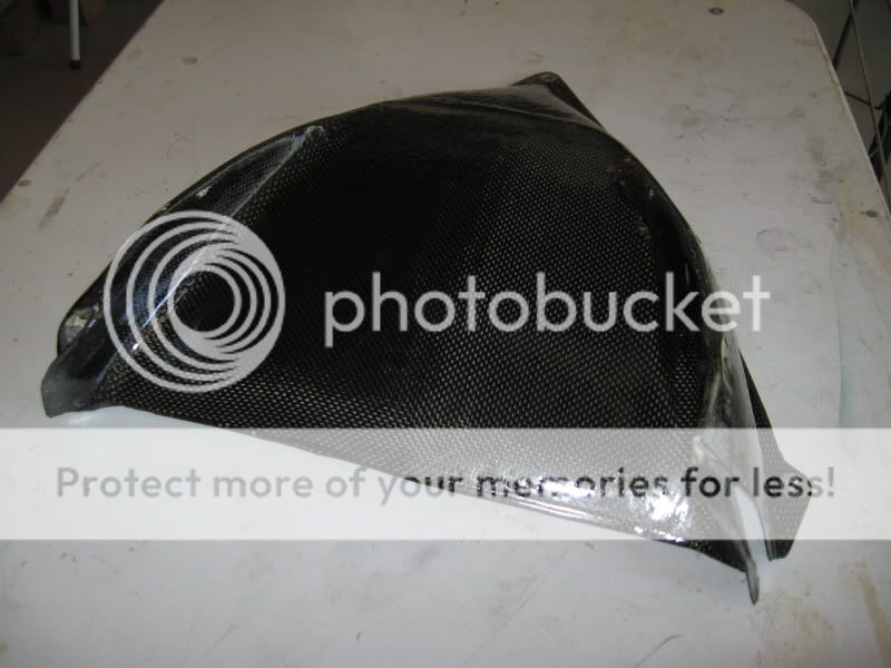
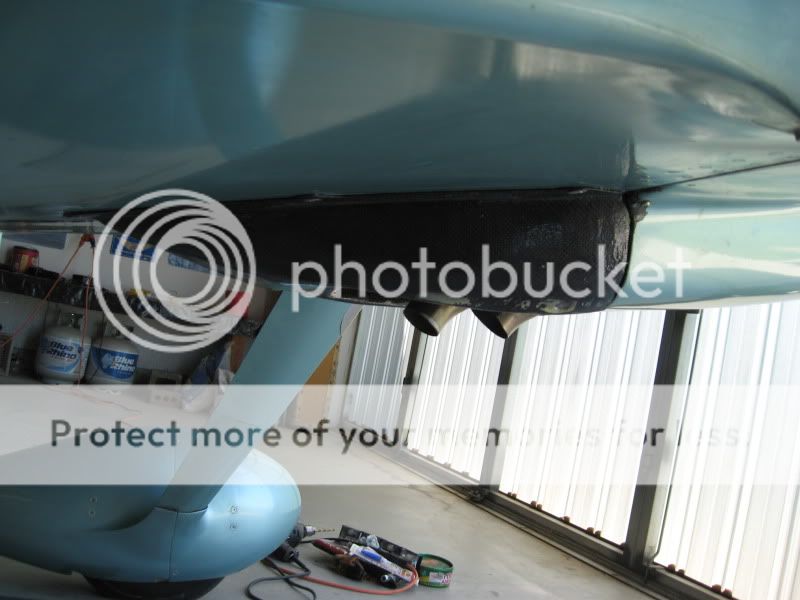
Last edited:
I have been working on another approach
to this same area. My approach will be much simpler with less structure. It is based on the concept of outlet "chimneys" that are currently in use in F1 auto racing to optimize engine compartment outlet flow.
My approach should get the outlet airstream accelerated to free stream speed efficiently with minimum turbulence. If this exit air is smoothed, there should be a drag reduction and also more efficient cooling.
From observation, I know that the corner of the outlets (where the cowl exit meets the fire wall) is extremely turbulent. Air in this corner actually flows back into the cowl. That area is my current focus.
I hope to have some of this work done (after visiting Osh Gosh) by the Indy SARL race. Pictures and results by then I hope.
This chasing speed thing is addicting!!
A true believer in the need for speed
Thanks for the information. I guess I'm going to have to exercise Google to find out what an F1 exhaust chimney looks like. I looked at the www.sportairrace.org "who's In" list for the Indy Air Race on August 13 and I see only 2 RVs (both RV-6s that I'm familiar with). Have you let them know you are racing yet? I hope to be back in the saddle by the end of the season or next year and it is always good to meet a new speeder.
Bob Axsom
to this same area. My approach will be much simpler with less structure. It is based on the concept of outlet "chimneys" that are currently in use in F1 auto racing to optimize engine compartment outlet flow.
My approach should get the outlet airstream accelerated to free stream speed efficiently with minimum turbulence. If this exit air is smoothed, there should be a drag reduction and also more efficient cooling.
From observation, I know that the corner of the outlets (where the cowl exit meets the fire wall) is extremely turbulent. Air in this corner actually flows back into the cowl. That area is my current focus.
I hope to have some of this work done (after visiting Osh Gosh) by the Indy SARL race. Pictures and results by then I hope.
This chasing speed thing is addicting!!
Thanks for the information. I guess I'm going to have to exercise Google to find out what an F1 exhaust chimney looks like. I looked at the www.sportairrace.org "who's In" list for the Indy Air Race on August 13 and I see only 2 RVs (both RV-6s that I'm familiar with). Have you let them know you are racing yet? I hope to be back in the saddle by the end of the season or next year and it is always good to meet a new speeder.
Bob Axsom
Mike D
Well Known Member
Some interesting reading on F1 exhaust
http://f1-dictionary.110mb.com/diffuser_blown.html
http://f1-dictionary.110mb.com/diffuser_blown.html
Howard, you like to calculate the efficiency of my propeller, so I'll give you a little comparison. Van's quotes the TAS of an RV-6 solo with 150 HP at 187 mph at 8000', which I would assume was 2700 rpm since it was supposed to be at 75% power. Jim got 186 mph with his Aymar DeMuth at 2798 rpm, and with my three-blade Ellipse it gave 190.5 mph at 2700 rpm back before he did any aero clean-up. I don't know what prop Van's used to obtain his data but I'm sure you know or could find out. As you know, the relative efficiency is based on (TAS1/TAS2)^3 X RPM2/RPM1. Just using these, its shown that the efficiency difference of the Ellipse ove the A-D is +11.3%. The Van's relative to A-D was +5.3%, and the Ellipse relative to Van's was +5.7%. Now with the wingtips and the cooling outlet fairing, Jim's plane at 202 mph is 26% more efficient than a standard Van's RV-6; that's like having 189HP but without the extra fuel flow.
Thanks
thanks Mike - That is a great source I had'nt seen.
The F1 world is a great source for this type of thing. They have huge budgets and do a lot of wind tunnel work and much of it is in the same speed range where we are - 180 mph or so with similar goals - air flow management for drag reduction or lift.
I am contemplating some diffuser work inside the cowl at the exit area -more to shape and direct airflow to get it out of the cowl efficiently, similar to what Bob has done but simpler, and similar to what the F1 guys do around the front wing and side pods and chimmneys.
I'll share as I go.
Fly safe!!
Last edited:
brian
Well Known Member
i wonder what the fairing cross-section is
I have a question about what the inside of that fairing is like. We have a pic of it looking forward, but not one of it looking aft. Is the fairing interior open to the aft of the cutout for the exhaust, or is it blocked off? It seems to me that, if it's open, the air coming out of the cowl will go in to the opening aft of the cutout, catch in that dead open space, swirl all around, and create drag as it comes dumping out. It seems to my seat-of-pants engineering that the fairing should have a vertical wall from the aft part of the cutout up to the belly of the aircraft, preferable one that slopes fwd at about 45 degrees, so the air coming from the cowl gets dumped smoothly into the airstream, rather than going into a dead space pocket. I hope I'm describing this clearly so you all can understand what I'm saying.
On similar note, I attended a "Reducing Drag" seminar by Jim Bede at OSH. One thing he mentioned was that slots in the back of wheelpants MAY help reduce drag by dumping the air caught into the wheelpant out to the aft, rather than having it swirling and pouring out as I described above for this exhaust fairing. The other big thing he mentioned was that any and all GAPS create drag, and that we should try to eliminate all the gaps we can.
Here are three of the photos I received. There are others in the sequence of Jim Smith's buildup but I think these show the product. He has smooth flow contours and that seem natural......
I have a question about what the inside of that fairing is like. We have a pic of it looking forward, but not one of it looking aft. Is the fairing interior open to the aft of the cutout for the exhaust, or is it blocked off? It seems to me that, if it's open, the air coming out of the cowl will go in to the opening aft of the cutout, catch in that dead open space, swirl all around, and create drag as it comes dumping out. It seems to my seat-of-pants engineering that the fairing should have a vertical wall from the aft part of the cutout up to the belly of the aircraft, preferable one that slopes fwd at about 45 degrees, so the air coming from the cowl gets dumped smoothly into the airstream, rather than going into a dead space pocket. I hope I'm describing this clearly so you all can understand what I'm saying.
On similar note, I attended a "Reducing Drag" seminar by Jim Bede at OSH. One thing he mentioned was that slots in the back of wheelpants MAY help reduce drag by dumping the air caught into the wheelpant out to the aft, rather than having it swirling and pouring out as I described above for this exhaust fairing. The other big thing he mentioned was that any and all GAPS create drag, and that we should try to eliminate all the gaps we can.
hevansrv7a
Well Known Member
Prop Efficiency
The CAFE flight's prop efficiency was most likely 78.8%. If it had flown at 8000' it would have needed 121.32 BHP to go 187 mph. To go 190.5 on the same BHP the prop would be at 82.5%. I did not use your formula because it is not completely accurate. The tool includes the drag polar and the density altitude. It's on my website and anyone can try this by downloading it and using it. The gain in efficiency from 78.8% to 82.5% is 3.7% which is correct in terms of BHP. But comparing them to each other, the gain is 82.5/78.8 or relative 4.7%.
CAFE used a Warnke 70 x 74 wood, fixed pitch prop. FWIW.
By way of comparison in a more general way, the Elippse prop on Jim's 6A is very close in efficiency, as best I can tell, to my Catto 3-blade on my 7A.
Since the A-D prop was at a different RPM and I don't have a really good way to evaluate the HP delta, I did not include it. That said, a minus 1 mph at a plus 3.6% RPM (full throttle or equal MP) is not favorable.
75% of 150 is 112.5. But, 121.32 is 80.8% of 150. This is consistent with what Kevin Horton found when he looked at the question of power versus altitude and all my work comes to the same conclusion. In other words, these numbers are probably right for a nominal 150 BHP engine at 8000'. Thus, they are consistent with the CAFE findings.
Many have pointed out that these are hand-build airplanes and must therefore vary. Yes, that is true. However, we need to assume a high degree of similarity, even in the 6 series which was not pre-punched (?). Comparing 7's, 8's or 9's would be even better because their alignments would be more nearly equal.
Anyhow, thanks for the additional data.
Paul, your (Jim's) numbers here are different than quoted at other times and other cases, but I did a quick look at these numbers. I used my triangle tool which has already been done for the CAFE 6A and which balances well to Van's data from his well known long-distance test as often quoted by Jack Norris. I did once inquire of Van's staff some details about the numbers he uses for the 6/6A and the answer I got suggested that nobody really knows anymore. I did not find that very helpful.Howard, you like to calculate the efficiency of my propeller, so I'll give you a little comparison. Van's quotes the TAS of an RV-6 solo with 150 HP at 187 mph at 8000', which I would assume was 2700 rpm since it was supposed to be at 75% power. Jim got 186 mph with his Aymar DeMuth at 2798 rpm, and with my three-blade Ellipse it gave 190.5 mph at 2700 rpm back before he did any aero clean-up. I don't know what prop Van's used to obtain his data but I'm sure you know or could find out. As you know, the relative efficiency is based on (TAS1/TAS2)^3 X RPM2/RPM1. Just using these, its shown that the efficiency difference of the Ellipse ove the A-D is +11.3%. The Van's relative to A-D was +5.3%, and the Ellipse relative to Van's was +5.7%. Now with the wingtips and the cooling outlet fairing, Jim's plane at 202 mph is 26% more efficient than a standard Van's RV-6; that's like having 189HP but without the extra fuel flow.
The CAFE flight's prop efficiency was most likely 78.8%. If it had flown at 8000' it would have needed 121.32 BHP to go 187 mph. To go 190.5 on the same BHP the prop would be at 82.5%. I did not use your formula because it is not completely accurate. The tool includes the drag polar and the density altitude. It's on my website and anyone can try this by downloading it and using it. The gain in efficiency from 78.8% to 82.5% is 3.7% which is correct in terms of BHP. But comparing them to each other, the gain is 82.5/78.8 or relative 4.7%.
CAFE used a Warnke 70 x 74 wood, fixed pitch prop. FWIW.
By way of comparison in a more general way, the Elippse prop on Jim's 6A is very close in efficiency, as best I can tell, to my Catto 3-blade on my 7A.
Since the A-D prop was at a different RPM and I don't have a really good way to evaluate the HP delta, I did not include it. That said, a minus 1 mph at a plus 3.6% RPM (full throttle or equal MP) is not favorable.
75% of 150 is 112.5. But, 121.32 is 80.8% of 150. This is consistent with what Kevin Horton found when he looked at the question of power versus altitude and all my work comes to the same conclusion. In other words, these numbers are probably right for a nominal 150 BHP engine at 8000'. Thus, they are consistent with the CAFE findings.
Many have pointed out that these are hand-build airplanes and must therefore vary. Yes, that is true. However, we need to assume a high degree of similarity, even in the 6 series which was not pre-punched (?). Comparing 7's, 8's or 9's would be even better because their alignments would be more nearly equal.
Anyhow, thanks for the additional data.
His implementation is similar to your description
Jim's fairing is curved and shaped to get the cooling air our in an orderly way - no traps or unnecessary changes in direction an no excess cross section. He told me it is actually the third generation of the cooling outlet fairing by Larry Vetterman. I can see the evolution and the improvement over the previous two designs. I intend to adapt the general idea on my RV-6A with the addition of a flap extending to the forward edge of the outlet. In otherwords I think it is a good design.
As far as cutting outlets at the read of the Landing Gear fairings, I think that is a bad idea that promotes airflow through the fairing from the large opening area around the tire through a restricted outlet. If you think about it I believe you will realize this is not a drag reduction thing. However if you think it has merit you should try it (like I did with the internal volume reducing bulkheads inside the front and back of the fairings - another bad idea).
I am currently involved in a 24 hr a day 7 day a week situation that is not an arbitrary choice but when this resolves I plan to cut the wingspan down by 18" giving a wingspan of 20' with 3" racing tips and make custom deep well wheel fairings based on my stock fairings and custom subfairings and make a cooling air outlet fairing similar to Jim's with a flap. We just keep struggling for knots.
Bob Axsom
I have a question about what the inside of that fairing is like. We have a pic of it looking forward, but not one of it looking aft. Is the fairing interior open to the aft of the cutout for the exhaust, or is it blocked off? It seems to me that, if it's open, the air coming out of the cowl will go in to the opening aft of the cutout, catch in that dead open space, swirl all around, and create drag as it comes dumping out. It seems to my seat-of-pants engineering that the fairing should have a vertical wall from the aft part of the cutout up to the belly of the aircraft, preferable one that slopes fwd at about 45 degrees, so the air coming from the cowl gets dumped smoothly into the airstream, rather than going into a dead space pocket. I hope I'm describing this clearly so you all can understand what I'm saying.
On similar note, I attended a "Reducing Drag" seminar by Jim Bede at OSH. One thing he mentioned was that slots in the back of wheelpants MAY help reduce drag by dumping the air caught into the wheelpant out to the aft, rather than having it swirling and pouring out as I described above for this exhaust fairing. The other big thing he mentioned was that any and all GAPS create drag, and that we should try to eliminate all the gaps we can.
Jim's fairing is curved and shaped to get the cooling air our in an orderly way - no traps or unnecessary changes in direction an no excess cross section. He told me it is actually the third generation of the cooling outlet fairing by Larry Vetterman. I can see the evolution and the improvement over the previous two designs. I intend to adapt the general idea on my RV-6A with the addition of a flap extending to the forward edge of the outlet. In otherwords I think it is a good design.
As far as cutting outlets at the read of the Landing Gear fairings, I think that is a bad idea that promotes airflow through the fairing from the large opening area around the tire through a restricted outlet. If you think about it I believe you will realize this is not a drag reduction thing. However if you think it has merit you should try it (like I did with the internal volume reducing bulkheads inside the front and back of the fairings - another bad idea).
I am currently involved in a 24 hr a day 7 day a week situation that is not an arbitrary choice but when this resolves I plan to cut the wingspan down by 18" giving a wingspan of 20' with 3" racing tips and make custom deep well wheel fairings based on my stock fairings and custom subfairings and make a cooling air outlet fairing similar to Jim's with a flap. We just keep struggling for knots.
Bob Axsom
digidocs
Well Known Member
Paul,
Thanks for taking the time to answer my previous question. I had to think about it for a moment, but I think I now have a pretty good grasp on your answer.
One follow up question:
What drives the design towards a larger number of blades? It seems that once you choose the design Cl (fixed Cd, airspeed, RPM), you can calculate the blade area required to produce the required thrust. This area could be distributed across 2, 3, ... 8 blades.
Also, the pointer to the new NP-2000 propeller was very interesting. They really do take the airfoils all the way to the (big) spinner/hub. Do you know of any experiments on how to seal a more traditional (read: Hartzell) CS hub design?
Or maybe you have a secret CS prop in the works. That would be cool.

