What's new
Van's Air Force

Don't miss anything! Register now for full access to the definitive RV support community.

RV-7 Andrew Z #73658

Of course, I then realized that I needed that area open so I could attempt to buck the four rivets outboard of that point. Drilled out that rivet.
At least I remembered to put some RTV along the back edge of the stiffeners.
20100721-018-large.jpg


After that, I got the skin clecoed on.
It's looking like something that slight resembles an airplane!
20100721-019-large.jpg

Another angle.
20100721-020-large.jpg


I'm kicking myself for not edge-rolling that one lap joint. I only remembered that I didn't when I woke up in the middle of the night. My two options are to leave it, or drill out 4 rivets and edge roll. Maybe I'll rivet the rest of the joint (two more rivets), then decide whether it is bad enough if the edge picks up at all. I don't think it will, but I'll start there so if I have to take it apart, it will only be a few rivets.

1 hour. 4 rivets, one drilled out.
Prev | Next
 
Post Title: Left Elevator Skin Riveting
Link to Post
Fri, 23 Jul 2010 22:47:39 +0000
Prev | Next

I wasn't very good with the pictures today, but I did get a significant amount of work done today. I basically did a lot of skin riveting, and all went well, with a few exceptions.

First up, try to use solid rivets on the outboard part of the trim spar where they instructions say you can use blind rivets.
"Blind rivets? We don't need no stinking blind rivets."
20100723-001-large.jpg


The top row (actually the bottom of the elevator) turned out well.
These aren't the prettiest or most perfect shop heads, but they are within spec, and will do the job.
20100723-008-large.jpg


Then, I flipped the elevator over and did the top (which was harder, but actually turned out better than the bottom). I forgot to take pictures though.

I moved on to the counterbalance skin and set have the rivets, then removed the clecos and set the other half.
Here's every other one set.
20100723-015-large.jpg


Wait a minute! I'm going to need that trim tab hinge (forward half) primed so I can rivet it on the elevator.
Up on the priming table for some self-etching primer.
20100723-016-large.jpg


Moving on to the rest of the skin, here are half of the rivets set in the leading edge and inboard edge.
Halfway done with one side.
20100723-017-large.jpg

Then I removed the clecoes and finished up the first side (except for the trim tab area).
20100723-019-large.jpg


After the hinge dried, I clecoed that in place and got to it.
Clecoed in place...
20100723-020-large.jpg

Half the rivets set, clecoes removed...
20100723-021-large.jpg

All done, with the tab half of the hinge installed to make sure I don't have any binding.
20100723-022-large.jpg


Then, I flipped that bad boy over and finished the other side.
IT LOOKS LIKE AN AIRPLANE PART!
20100723-025-large.jpg


Wow, big day today. 172 rivets, four of them drilled out. (Notice how I just glossed over the riveting of my trim riblet? That's because it was about an hour of my two hours outside. What a pain in my aft.)
Prev | Next
 
Post Title: Rolled Left Elevator Leading Edge
Link to Post
Sat, 24 Jul 2010 22:24:49 +0000
Prev | Next

Well, today was just a barrel of rainbows and puppy dogs. Lucky me, I got to mangle the project per the directions.

It's funny. The directions say <em>"roll and rivet the leading edges."</em>

Hmm.

Sounds easy.

If I were writing the directions, it would go something more like this:

<em>"1. After spending 50 man-hours carefully protecting all of the aircraft-grade aluminum from dents, scratches, and general mistreatment, duct-tape a steel rod to the inside of the leading edges and use ALL OF YOUR MIGHT to roll that sucker around. You won't be able to make the roll anywhere close to acceptable the first time around, so be prepared to curse and fight your way by hand squeezing the two edges together to get clecos into the holes that have been so generously provided for you. Then, rivet the two surfaces together, but only after realizing that the clamping force of the clecoes was helping everything line up, so pray that as you set the blind rivet, it will pull everything back to alignment. </em>

<em>2. After riveting, stand back and realize that on one of the sections, you forgot to edge-roll one edge, so there is a slight puckering between two of the rivets, but don't worry yourself about it too much, because although it will keep you up at night, no one else will see it once the elevators are mounted to the horizontal stabilizer.</em>

<em>3. Stab yourself in the eye with a cleco, and then try not to bleed into the adult beverage of choice that you have now earned."</em>

<emspan style="font-style:normal;">There. Wasn't that fun?</span/em>
The outboard-most section, rolled and clecoed.
20100724-001-large.jpg

Middle section rolled. You can see how bad my roll is on the rightmost edge. (You can also see how I tape the skin to the steel bar.)
20100724-002-large.jpg

3 of 4 sections clecoed.
20100724-003-large.jpg

I took a break from rolling and installed my rod-end bearings. This tool works great. (I could have made it a lot shorter, though.)
20100724-004-large.jpg

Finally, all the leading edge rivets installed. Time for a drink.
20100724-005-large.jpg


2 stinking hours for this? 22 rivets, one (actually painless) blind rivet needed to be drilled out.
Prev | Next
 
Post Title: Rolled Right Elevator Leading Edge
Link to Post
Sat, 31 Jul 2010 18:57:55 +0000
Prev | Next

How exciting! I get to roll the right elevator leading edge today!

Okay, if you couldn't sense the sarcasm there, I'll lay it out for you. I hate rolling leading edges.
This first section actually turned out nice after the roll. It was pretty easy to squeeze these together and rivet.?
20100731-005-large.jpg

See? EasY!
20100731-006-large.jpg


Then, I took a picture of how I tape, which I have since ammended.
Now, I put tape along the entire edge, overlapping once piece with another.?
20100731-007-large.jpg


Of course, since things started going badly, I forgot to take more pictures, but rest assured, I have some unintentional puckering between rivets on one of my rolled sections. The crappy thing is that once you roll and remove the pipe and tape, it is really hard to go back and re-roll.

Anyway, I moved on to installing the rod-end bearings.
Here is my rod-end bearing tool.
20100731-008-large.jpg

You can see how the rod-end just fits right in there. (The purpose of the tool is to help turn the rod-end in the nutplate without putting any pressure on the actual round bearing in the center.)
20100731-009-large.jpg

Tightening.
20100731-010-large.jpg


They want you to install the elevator rod-ends to 13/16".
That's 13/16".
20100731-011-large.jpg

Right on the money.
20100731-012-large.jpg
 
After getting those in, I set the elevators aside and moved back to the trim tab. Here, I'm using wood backing (so the pilot of the countersink cutter has a good guide) and countersinking the holes on the top of the spar only (you can't dimple the top, because the hinge sits just underneath the spar flange).
I'mi using a scrap piece of wood flooring here.
20100731-015-large.jpg


Then, it was time to dimple the skin. I only got the tab to a place where I can cleco it back together. I still have to fabricate some trim tab riblets.
Dimpled tab skin.
20100731-016-large.jpg


Then, I dragged the horizontal stabilizer out of the storage room and installed the elevators. Once I realized I had to drill out the hinge brackets to #12, the bolts went right in.
It looks like an airplane. And it's huge.
20100731-017-large.jpg


I'll take more pictures of it for you sometime, but for now, I'm just going to leave this assembly on the workbench for a few days and admire it.

3 hours today. 22 more rivets.
Prev | Next
 
Post Title: Low point of the build
Link to Post
Wed, 11 Aug 2010 01:30:07 +0000
Prev | Next

Well, today was the low point in the build so far.

I was fiddling around with the empennage, trying to set it up to look like a tail for the "completed empennage" picture everyone posts, and I dropped the rudder.
horrified silence]

It hit on the bottom aft edge, bounced a little, and then hit in the top rear edge.
Oh god, oh god, oh god.
20100810-001-large.jpg

Prev | Next
 
Post Title: Made a Decision on the Rudder
Link to Post
Thu, 12 Aug 2010 16:33:31 +0000
Prev | Next

Disclaimer: My favorite tag for today's post is "Boo Boo boom boom airplane go fly." Read on.

Well, after much soul searching, and some really helpful advice from VAF (thread here), I'm going to drill out the skins, inspect for any internal damage and rebuild the larger rudder.

Favorite quotes from the thread:

<blockquote>
?I did the SAME EXACT THING as you did
?I dropped a completed fuel tank while moving it from one storage location to another.
?My two year old daughter says "Boo Boo boom boom airplane go fly" while looking at your rudder. I am so proud!
?I forgot the fiberglass tips were on and unsecured. He picked up one end and --crash!
?I banged up my rudder too.
?Don't feel bad - I had to build a whole second set of ailerons when I built them both backwards, at the same time (DOH!)
?Your new rudder will be better than the old one.
</blockquote>
</ol>
Although I got my hands on a set of RV-8 rudder preview plans, and a lot of the parts are common, I just don't want to mess with doing a large flight test spin program just for aesthetics. It just doesn't seem like the right thing to do.

While I could probably say I'm not going to intentionally spin the airplane, I probably will want to at some point, and I'm really worried about having a botched aerobatic maneuver (too slow during a hammerhead turn), and falling off into a spin from which I'll have a hard time recovering. In that case, I'll want the bigger rudder.

Also, I would feel guilty ever selling the airplane, especially if (god-forbid) anything ever happened to a later owner.

So, rebuilding the larger rudder it is. And besides, my trailing edge is going to be perfect this time.

But, in the meantime, I want to set the new standard in "finished empennage pictures." Maybe this new standard will keep someone else from damaging their airplane for the sake of a stupid picture.
Done with the empennage!
2-15-10-002-large.jpg


Now where is that wing kit?
Prev | Next
 
Post Title: Started Drilling Out Rudder
Link to Post
Sat, 14 Aug 2010 18:00:38 +0000
Prev | Next

Well, after much hand-wrenching and a few sleepless nights, I've decided to dive into taking the rudder apart to assess the damage.

I'm guessing there are a few hundred rivets I need to drill out, which is going to ruin my drilling out average, but that's okay. I want the rudder to be perfect. The pictures aren't really that exciting, but here they are anyway.
About the first 25 after they've been drilled out.
20100816-008-large.jpg


I started drilling out the leading edge blind rivets. They ended up not being that bad, but not something I ever really want to do in the future.
Started drilling out leading edge rivets.
20100816-010-large.jpg

I ended up using a #40 drill bit for the blind rivets, even though they are really #30 sized holes. #40 allowed me to pry the heads off really easily. (You can see the heads of the blind rivets on the table.)
20100816-011-large.jpg

67 rivets drilled out, and I'm now dripping sweat on the rudder. Time to go inside.
20100816-012-large.jpg


But just for kicks, I took a picture of the rudder skin after pulling off one of the blue vinyl sections.
It's going to look really good when I take the vinyl off of the whole airplane. (You can see the outline, though, which means I'll still need to do a little polishing before first flight.)
20100816-013-large.jpg


It was about 30 minutes in the garage for just this part. I'm trying to figure out if I want to keep going on this or start in on the wing kit. For sure, I'll need to finish the elevator trim tab before moving on to the wing. Maybe I'll put the rudder away for awhile and move on.
Prev | Next
 
Post Title: Christmas in August (Wing Kit Arrived)
Link to Post
Mon, 16 Aug 2010 20:00:58 +0000
Prev | Next

OH MY GOD OH MY GOD OH MY GOD....IT'S HERE!!!!!
Oh man, I really need to edge the driveway.
20100816-016-large.jpg

Judge how excited I am by counting the number of truck pictures I took.
20100816-017-large.jpg

This is number three!
20100816-018-large.jpg


asdf
Whoa. Full load today? (Those boxes look so little!)
20100816-020-large.jpg


So we picked up the larger (wider) box, and it was (I'm guessing, here) about 150 lb. No problem for the driver and I to bring it into the garage.

Then, we picked up the small (but long) box, and it was (probably exaggerating) about 300 lb. I felt stupid grunting and groaning trying to lift this box. It was deceivingly heavy.
Finally home.
20100816-021-large.jpg
 
Luckily, all the parts were completely undamaged. That rhino-poke through the spar box when right into a big block of paper separating the center section pieces from the main spars. I am a lucky son-of-a-gun.
Tops off, time to start unpacking.
20100816-027-large.jpg

Here's another rhino-poke picture.
20100816-028-large.jpg

The backside.
20100816-029-large.jpg

Redundant, but better light.
20100816-030-large.jpg


First thing, I got everything out of the boxes and onto the carpeted floor and workbench. That is a lot of paper. As Brad Oliver put it:
<blockquote>"there is $100 worth of aluminum and $5000 worth of paper in these boxes"</blockquote>
I couldn't agree more.
Whoa. Paper!
20100816-031-large.jpg


After getting everything out and onto the carpet...
That's a lot of parts.
20100816-034-large.jpg

Tank and leading edge skins.
20100816-036-large.jpg

I managed to stick the longerons against the (very messy) back wall of my garage.
20100816-038-large.jpg
 
Upstairs, I have an extra room devoted to airplane storage (and working out, and music).
The wingtips are HUGE!
20100816-039-large.jpg

Tank and leading edges upstairs.
20100816-040-large.jpg

I also took these upstairs. These go with the fuselage, but they are matchdrilled at the factory with the spars, so they ship them all at once. Good thinking.
20100816-041-large.jpg

This is normal, but just wanted to note a few places where they used a scotchbrite pad to buff out some scratches.
20100816-042-large.jpg


Time to start the inventory. 5 pages of inventory sheets for the main kit, then 5 more for the hardware, and a few more here and there for the aileron mounting kit, and the stall warning kit.
{sigh} This is going to take forever.
20100816-043-large.jpg


Looks like the only problem was that I got 5 W-712-L ribs and 1 W-712-R rib instead of 3 of each.

Most of the ribs in the kit were sandwiched L and R ribs, but some of these sets were sandwiched L and L ribs.
Too many lefts, and not enough rights!
20100816-045-large.jpg


Drumroll please! {drumroll sound}
Tada! The beautiful (and expensive) deluxe locking fuel caps. With four keys, of course.
20100816-046-large.jpg


I decided to go with the tried and true float senders, mostly because I didn't want trouble with the capacitive senders (which work well only with 100LL gas. If you ever change types of fuel, they won't work correctly.)
I'm sure these are fine, but they are a little "cheesy" (as a coworker who also has them put it).
20100816-047-large.jpg
 
After about 3.5 hours of work, most of the parts have new homes under my workbenches or upstairs in the airplane room.
Tightly packed parts.
20100816-048-large.jpg


Next up, time to inventory the hardware.
I hope it all fits.
20100816-049-large.jpg


But first, time for some dinner.
It's Monday. Why not have steak, grilled corn on the cob, and a homemade caprese salad? (Look at those Bobby Flay grill marks!)
20100816-050-large.jpg


Okay, after dinner, I sat myself down in front of the TV and worked more on the hardware inventory. The only thing that didn't really fit well into my sorting scheme was the AN426AD3-3.5 rivets. There were way too many in the wing kit for my smaller sized container.
In the background, you can see one of the 5 (?) hardware inventory pages.
20100816-053-large.jpg


After another hour and a half, almost all of the hardware now has a home in my fancy hardware cases.
The close tolerance bolts didn't fit, so I'm going to leave them in the bag for now.
20100816-054-large.jpg


Finally, I took a picture of all of the inventory sheets. I have horrible handwriting, but you get the idea.
Those all say "page done."
20100816-055-large.jpg


3.5 hours to most of the bigger parts inventoried, and 1.5 more hours to do the hardware. 5 hours total. Feels great to have the wing put away safely.
Prev | Next
 
Post Title: More Trim Tab Work
Link to Post
Tue, 17 Aug 2010 21:21:12 +0000
Prev | Next
[URL="http://n999za.wordpress.com/2010/08/17/more-trim-tab-work/">[/URL]Well, before I can dive into the wing, I need to finish up the trim tab. All that's left is to fabricate two riblets, get everything prepped and primed, and then rivet the tab together.

First, let's get some riblets made up. Just like the elevator riblet, I started with some thick paper.
I used the packing list envelope from the wings, because it was literally right in front of me when I started.
20100818-001-large.jpg


I got the larger one cut out of 0.025" aluminum sheet pretty easily, and the first try fit like a champ. I moved on to the smaller one, hoping for similar luck.Fast forward a couple minutes (many minutes!)...
Can you say "third time is a charm?"
20100818-002-large.jpg


Nope. Third one wasn't good either.
Let's try again (fourth time). I just couldn't get the bends right.
20100818-003-large.jpg


That one worked. And of course I forgot to take a picture.
I drilled a couple holes in each riblet through the skin.
20100818-004-large.jpg


Finally, fourth time is a charm.
Wuhoo, let's get this tab finished.
20100818-005-large.jpg


But, it was getting late, and there were a couple of puppies somewhere that needed attention. (Turned out, they were asleep when I went inside, and I got growled at. Thanks, puppies.) Before I headed inside, I disassembled the tab and pulled out the wing spars to inspect.
Tab components, ready for cleaning and priming.
20100818-006-large.jpg


After looking the spars over, I found many places where the spars had been "polished" with a scotchbrite bad to work out small scratches. It seems that everyone has these, and is no cause for alarm.

On the other hand, I found some bad juju. This is a closeup of a couple dings that look like something bounced on the spar. Keep in mind, that hole is a #40 (3/32"), so these are really small.
Still, that's not good.
20100818-007-large.jpg


Whoa. What. Is. That!?
Holy frijoles, Batman! That is a huge dent in my spar flange!
20100818-010-large.jpg

Here's a closeup of the dent with a straightedge held over it.
20100818-011-large.jpg

Another angle.
20100818-012-large.jpg
 
I took a couple pictures of the underside of the flange. I tried to use the light to demonstrate the distortion.
That curved white streak is actually the light reflecting off of some spider cracks in the anodizing.
20100818-008-large.jpg

Here's another angle.
20100818-009-large.jpg


Not really related, I just snapped a picture of the spars laying on the table.
At least they look pretty.
20100818-015-large.jpg


1.5 hours on the trim tab today. I'll email Van's first thing in the morning about the spars and then post what they say.

I'm pretty disappointed though. Nothing could create that dent without making a big noise, maybe something being dropped or falling over. Which means someone probably knew it happened and didn't say anything, or the inspection process didn't catch it. Either way, I'm not super excited. I'm guessing it wasn't Vans' fault, but hopefully they will make it right.
Prev | Next
 
Post Title: Primed Elevator Trim Tab
Link to Post
Fri, 20 Aug 2010 02:00:35 +0000
Prev | Next

Well, I got a few more things done on the tab tonight.

First thing was to prime the outside of the elevator tab where the surface mates with the tab horns.
Here's the mating surface, ready to be primed.
20100819-001-large.jpg


After reexamining my countersinks in the trim tab spar, I decided to re-countersink them. This time (after reading the guidance in the construction manual about how to do this on the flap), I used the trim hinge as a countersink guide. This worked much better than the piece of wood.
Nice countersink on the left. The old (wobbly) countersink on the right.
20100819-002-large.jpg


Then, everything was put up on the cardboard piece for priming.
Priming.
20100819-003-large.jpg


After the parts dried, I started in on riveting per the plans.

Everything was fine after 7 rivets, until I paused to re-fit the tab on the elevator.
4 of the first 7.
20100819-004-large.jpg


I was getting a little bowing (top skin concave, bottom skin convex) in the tab skin due to what appeared to be distortion of the tab spar. I drilled out the 7 rivets I had set and spent a little time re-tweaking the spar.
A fit check. You can't see any of the bowing very well, but it is definitely not satisfactory.?
20100819-005-large.jpg


After re-tweaking (adjusting the spar flanges on the tab) and refitting a few times, I had things lined up much better. It's not perfect yet (maybe more work on this tomorrow will get it right), but it is definitely improvable.

1 hour today.
Prev | Next
 
Post Title: Finished Trim Tab
Link to Post
Fri, 20 Aug 2010 21:09:06 +0000
Prev | Next
Well, I snuck home over lunch today to make some loud noises (rivet gun) and I got the trim tab pretty much finished. I have one or two more "hard to reach" rivets to set, but for now, I'm going to call it done and focus my attention on the floors and the wings.
The tabs bottom rivets.
20100820-002-large.jpg

Here's the bottom of the tab.
20100820-003-large.jpg


Then, making sure to include the hinge (other builders have forgotten when the time comes to rivet), I got the top of the tab completed.
I do love those gold spars in the background.
20100820-004-large.jpg


Okay, so I'm a dork, and I had to get the hinge pin out and get the thing assembled.
Tab in trail...
20100820-005-large.jpg

Up tab (down elevator trim).
20100820-006-large.jpg

Down tab (up elevator trim). I still have some interference here from the shop heads of the bottom elevator rivets, but I'm going to wait until I'm rigging to sort this out any further.
20100820-007-large.jpg


A quick hour over lunch. 34 rivets set, 2 drilled out.
Prev | Next
 
Post Title: Bought Cleveland Main Squeeze
Link to Post
Sat, 21 Aug 2010 14:05:36 +0000
Prev | Next

Recently, I've been kind of unhappy with my economy squeezer that I bought from the Yard. (I think Avery sells the same squeezer).

The squeezer is great for the majority of tasks on the empennage, but it only has one yoke, and I really need a no-hole yoke for some of the tighter-access areas at the end of ribs and such.

So, to buy a no-hole yoke, it looks like I'm going to have to buy a new hand squeezer (insert long back and forth about pneumatic squeezers here. I'm okay with hand-squeezing for the whole airplane, but I want one that can exchange yokes with a pneumatic squeezer if I decide to get one in the future).
So, for no small chunk of change (thanks, savings!) I got Cleveland's Main Squeeze model 22 and the 4" Thin-Nose Pneu. Yoke. I won't be able to use this yoke for dimpling (still have the economy squeezer for that), but this will be great for squeezing rivets.

Aug 27, 2010 Update:

My new squeezer showed up. The actual squeezer is unbelievably light, and the yoke is unbelievably heavy. Even before installing the yoke, I can tell this is a much higher quality tool than my "economy" squeezer.
Here are the two separate purchases from Cleveland.
20100826-001-large.jpg

Ready for ACTION!
20100826-002-large.jpg


This should give you an idea of the difference in quality between the two.

In addition to being easier to squeeze, I am most impressed with the yoke. While I was squeezing rivets with the smaller 3" yoke, sometimes the yoke would "give" a little. I can only describe this as the "c" part of the yoke opening ever so slightly. This had the result of pulling the top of the yoke back just a little, sometimes shifting the shop head a little to one side, or in some cases, sliding the flush set along the manufactured head side during squeezing. Most of the rivets turned out okay, but I no longer have this problem with the new yoke.

Here's a picture of SRS (shifting rivet syndrome).
Big difference in quality (pronounced "price reflects this") and operation.
20100826-003-large.jpg


Bravo, Cleveland.
Prev | Next
 
Post Title: Right Spar Countersinking and Nutplates
Link to Post
Sun, 22 Aug 2010 20:30:57 +0000
Prev | Next

Well, today was the first official wing construction day. While Van's is trying to figure out what to do with my damaged left spar, I figured I should get started on the right spar.

First thing...yup...a plans change picture!

The plans for the wing are a little different. There are about 4 separate sheets of different views for the wing. You guys get to see just the general layout one.
Wuhoo! A wing!
20100822-009-large.jpg


Now, let's get to work. First thing, I very carefully put my beautiful right spar on the edge of the workbench and clamped the flange down very lightly. The spar will tip over onto the table (away from the camera) if the clamps let go, so I'm not too worried about clamping them down too much.

Every builder that has a website makes a comment here about how the construction manual really holds your hand and steps you through the process on the empennage, but then kind of just makes general statements for the wing. For example, the only real construction step on the first page of the wing section says:
<blockquote>"To begin wing construction, rivet the tank skin attach platenuts to the spar as show in DWG 16A, Detail A. Machine countersink the platenut attach holes in the W-706A spar flange."</blockquote>
Wait. What? That is like 1000 steps, condensed into one statement. It ended up taking me 3.5 hours to do that one step (I admit, I also delved a little into a step a few steps down):
<blockquote>"Attach the K1000-06 platenuts for the W-822 access plate to the W-706A flange. See DWG 12."</blockquote>
Fine. I see how it's going to be.

Let's get started.
Where is my countersink?
20100822-001-large.jpg


A lot of builders start out thinking they should make a nutplate jig and countersink the screw holes before riveting the nutplates (sorry Van, I call them nutplates) on so they can use the jig as a guide for the c/s pilot to avoid chatter. Van's suggests using the installed nutplates as the pilot guide. After those builders spend some time making those jigs, they eventually abandon the idea and fall back to the Van's method. I'm going to do something I don't normally do and FOLLOW THE INSTRUCTIONS. Sometimes, I try to get cute with extra ideas and fancy engineering solutions, when really I should just do things by the book.

So I grabbed my countersink with a #40 c/s bit, tested in some scrap, and positioned the countersink cage over one of the nutplate attach holes.

The c/s pilot didn't fit. What?!

You mean I am going to have to drill all of these holes out to #40 first? Ugh!

After drilling every one of the attach holes out to #40, I finally got the countersink and cage loaded back into my cordless drill (slower and more trigger feathering ability than the air-drill) and got to it. Here are my first 10 countersinks.
The blue tape is to prevent metal shavings from getting lodged in between the spar cap bars and the spar web.?
20100822-002-large.jpg


Phew, that was a lot of countersinking. (I think I counted 144 total countersinks for just the nutplate attach holes. There's another 72 for the screw holes (in the middle of each set of three holes) I'll have to do later.)

Next, I grabbed some K1100-08 nutplates, some silver 3/32" clecos, and some AN426AD3-4 rivets and started getting ready. My plan is to cleco the nutplate to the spar, insert one rivet, then after riveting that one, take the cleco out and rivet the other side.
Cleco in one side, unset rivet in the other.
20100822-011-large.jpg

Down the line, everything ready to rivet.
20100822-014-large.jpg

Redundant picture.
20100822-015-large.jpg
 
Ahh, this slower, more thoughtful approach is paying off. Can you see the error that I almost made?
Which one of these is not like the other?
20100822-017-large.jpg

Here's an example nutplate before I take the cleco out and put the other rivet in.
20100822-018-large.jpg


I can't remember why I took this picture. I think I just took out all the clecos, and I thought it looked cool.
Ready to set the second half of the rivets.
20100822-021-large.jpg


No pictures of the second rivets, but here's one of the other (now top) flange.
You can see all of the nutplates on the lower flange.
20100822-022-large.jpg


Anyway, I set all the nutplate attach rivets on the upper flange, and then called it a day. So I got to cross off the two statements in the construction manual I highlighted above, and next up is to use the installed nutplates as c/s pilot guides for countersinking the screw holes.

Oh, and then I get to repeat on the other spar.

3.5 hours of countersinking and riveting today. 144 rivets, 1 drilled out (the rivet split in two!). Good times.
Prev | Next
 
Post Title: Finished Countersinking Right Spar Flanges
Link to Post
Wed, 25 Aug 2010 02:00:17 +0000
Prev | Next

Well, tonight wasn't a long night in the shop, but it was a good night.

First of all, there was a package sitting on my doorstep when I got home from work. After the excitement for my new Cleveland Main Squeeze died down as I realized the package wasn't from Cleveland Tools, it quickly came back when I realized it was the missing W-712-R ribs that I had been shorted (what a cruel world!) in my wing kit.

Who knew I could get so excited about wing ribs.
Drumroll please!
20100824-001-large.jpg

{Triumphant music}
20100824-002-large.jpg


Okay, Andrew. Time to settle down.

Let's finish up this right spar flange countersinking.

From the first issue of the 2005 RVator (thanks to Brad Oliver, for the link) and to A VAF Post (again, thanks Brad), I was able to make this cute little HTML table for you.

From the first 2005 issue of the RVator (page 10):
"We countersink until the top of the screw is level with the surface, then go 2 clicks deeper on the microstop. The actual outside diameter of the countersink measures .365" to .375"."

Countersink Widths for Numbered Screws
Screw Size: Width [in]
#6: 0.3125
#8: 0.365-0.375

So, I broke out my trusty digital calipers, zeroed them out, and dialed in .370" (right in the middle of 0.365" and 0.375").

Just for kicks, I thought I would show you how much bigger that is than a #8 screw. The larger size allows the dimpled skin to nest nicely in the countersink.
WHOSE TOES ARE THOSE!?
20100824-004-large.jpg


SOMEBODY'S TOES KEEP GETTING IN MY PICTURES!

Anyway, I proceeded with countersinking the tank skin attach holes only (the access plate attach holes are smaller.) I am following the directions here exactly, using a #30 piloted countersink (which nestles nicely in the #8 nutplate) as my guide.
I stopped and verified the countersink depth every few holes. Looking good!
20100824-005-large.jpg

About halfway done with the bottom flange.
20100824-008-large.jpg


Finally, I finished with the bottom flange. (Notice the three sets of four countersinks on the right side of the picture. Those are for the access plates. They use a #40 piloted countersink and are countersunk to a width of 0.312" (which is less than 0.3125")).
Ta da!
20100824-013-large.jpg


1.0 Countersinking-filled hour tonight.

And, I've finished the first three paragraphs of the wing section of the manual. Score!
Prev | Next
 
Post Title: Started on Right Wing Tie-down Bracket
Link to Post
Fri, 27 Aug 2010 00:00:58 +0000
Prev | Next

Wuhoo, the new squeezer showed up!

After a few minutes of messing around with it, I grabbed the two K1000-4 nutplates and studied the plans carefully on which side of the spar they go. A quick hint (other than just reading the plans) is that the nutplates go on the side that couldn't possibly need to be flush (in between the spar cap bars).

Anyway, here, I've countersunk for AN426AD3-6 rivets.
The two larger holes are examples of where Van's (or Phlogiston) buffed out some spar scratches with some scotchbrite.
20100826-005-large.jpg


Oh yeah, I also flipped the spar over and deburred (you can hardly see the deburring) the backside of the holes I drilled to #40.
The little silver rings are where I deburred. Because these will be totally covered by the nutplate and the shop head, I'm going to refrain from spot priming them.
20100826-006-large.jpg


I used the new squeezer to set my only 4 rivets today.
Don't these look pretty? (There are small rings around the rivet heads. That is from the cleco I used to hold the nutplate on while riveting the other side.) It seems weird the cleco made that little mark.
20100826-007-large.jpg


Moving on to the tie-down bracket. First thing, I need to fabricate the W-726 spacers from this 1.25" wide angle stock. I'm supposed to cut 4 of them, 2 for each wing/tie-down).
Why is this one on the ground? Is it because the light is good for the camera? NO. It's because it is @&*!@ hot after cutting. Ask me how I know.
20100826-009-large.jpg

Here are the other three.
20100826-010-large.jpg


Each of these spacers should have a 1" hole cut in the center for lightening (not lightning). Since all of my hole saws are in sizes other than 1", I decided to grab the W-731 tie-down bracket and get to work on that.

Okay, the manual says to cut the tie-down bar to length from the AEX stock.

Okay (...searching plans...), looks like 7 15/32". Of course, I measured 7 7/32" marked, and almost cut before my gut told me something was wrong.
The bar is actually 7 16/32" ( or 7.5"), so I'm not going to cut them 1/32" when I'm sure the edge finishing on the scotchbrite wheel will be more than enough. (Also, it doesn't appear the extra 1/32" will interfere with the top or bottom skin at all.
20100826-011-large.jpg


I keep walking by this sticker and laughing. I thought I would share.
Translation: "If something doesn't fit right, you've royally screwed something up."
20100826-012-large.jpg


Okay, back to the tie-down. After marking and drilling the one (of four) holes for the spar in the bracket to 3/16", I stuck an AN3-7A bolt in there and just eyeballed the alignment.

(You are supposed to drill just one, then fit the bolt through the whole assembly. Then, you flip the entire assembly over and matchdrill the tie-down bracket from the back.)
I was a little concerned that there was some overhang on the right side of the bracket. (I measured and drilled very, very carefully).
20100826-013-large.jpg

Looks like there is some overhang on the plans, too. Sweet.
20100826-015-large.jpg


Anyway, I stopped there because I can't really matchdrill everything until I get the spacers placed behind the tie-down bracket, and I can't really do that until I have the lightening holes drilled (the spacers will be riveted to the tie-down brackets in four places, which in turn hold some nutplates on).
Here are my spacers for the right tie-down bracket.
20100826-016-large.jpg


1 hour, 4 rivets.

Now, I need to find a good hole saw or fly cutter.
Prev | Next
 
Post Title: More Right Tiedown Work, Started Right Rear Spar
Link to Post
Sun, 05 Sep 2010 16:44:47 +0000
Prev | Next

Whoa, it's been awhile since I actually got any work done on the airplane. I'm going to blame my exploding lawnmower (long story), business trips, and the wood floors project.

Anyway, I managed to find a good bi-metal hole saw from the aviation department at Lowe's, so I chucked that thing up in the drill press and started in on the spacer lightening holes.
Under all that mess is a spacer with a freshly cut hole in it.
20100905-001-large.jpg


I am not really a fan of cutting those things this way, but I don't have a fly cutter (apparently the one from Harbor Freight sucks), so this was the best I could do.

They actually turned out really nicely.
Two spacers, that go against the spar web.
20100905-003-large.jpg

Like many other builders, I taped them down before putting the tiedown bracket in place, flipping the spar over, and matchdrilling the remaining 7 holes.
20100905-004-large.jpg

After everything has been matchdrilled, I pulled it apart. Looking good so far.
20100905-005-large.jpg


Then, I skipped a couple pictures, but basically You bolt the tiedown bracket, spacers, and nutplates in place and use the nutplates to backdrill the attach holes (small ones on either side of the bigger holes). They all turned out great, except for the upper left set, which for some reason are a little crooked. It doesn't matter what the nutplate ear orientation is, I was just annoyed they didn't turn out perfectly aligned.
Somehow that upper left one's alignment got away from me.
20100905-006-large.jpg


Then, you have to countersink the nutplate attach holes (this side of the spacers must sit flush against the spar web).
These rivets aren't set (I still have to prime all these pieces), but I just put them in there to see how my countersinks were. (The lower left one is a little deep, but this is thick spacer, so it shouldn't be a big deal.)
20100905-007-large.jpg


I don't have any primer, so I decided to move forward ("aft"?...ha...airplane coordinate system joke) to the rear spar. After getting out the W-707A rear spar channel (make sure to grab the correct one, there's a left and a right) and the W-707E and W-707F doubler plates, I took the blue plastic off of everything and started getting things clamped in place.
The W-707F is laterally aligned with the outboard edge of the rear spar channel.
20100905-008-large.jpg

The W-707E gets laterally aligned by measuring; the outboard edge of the doubler plate should be 50 3/4" from the outboard edge of the rear spar channel. Easy enough.
20100905-010-large.jpg


Then, I fired up the air drill for some matchdrilling.
{air drill noises} Whose finger prints are those?
20100905-012-large.jpg

{more air drill noises} Also, I traced out the aileron pushrod hole onto the doubler plate.
20100905-014-large.jpg
 
After some though about how to do this, I decided to forego the step drill (Unibit) trick (I don't have a Unibit...how's that for a trick!) and just drill some holes and then get the dremel out.

It turns out that all the little fancy metal saw and milling tools aren't really as easy to use as the 1/2" sanding drum . Save yourself some time and just get the sanding drum out. Very easy to control.
Looks pretty good to me. (This crazy little torture device that looks like a saw got away from me and cause that scratch. I'll have to buff that out.)
20100905-015-large.jpg


After clecoing back to the spar turns out the thickness of my line made my initial pass a little small. (Better small than big.)
More sanding, anyone?
20100905-016-large.jpg

Much better (still needs some edge finishing).
20100905-017-large.jpg


I totally forgot. Even though I don't have primer to finish up the tiedown bracket, I can still tap the tiedown hole.
Here's the 3/16" x 16 tap.
20100905-018-large.jpg


After having a **** of a time getting started, they turned out really nicely.
1 full turn in, 1/2 turn out. Wash. Rinse. Repeat.
20100905-019-large.jpg


I managed to get both brackets done, even though I really haven't started on the left wing yet.
I'll need to deburr the edge, but this should work just fine.
20100905-022-large.jpg


I ended up going to 1 1/4", even though the directions tell you to only go 1". Some other builders had to go deeper once they actually got their eye bolts, I figured it would be easier to do now than to wait until the brackets are in the wings.

2 productive hours today.
Prev | Next
 
Post Title: Right Rear Spar Doubler and Reinforcement Fork
Link to Post
Thu, 09 Sep 2010 01:15:59 +0000
Prev | Next

The next step on the rear spars is to trip the W-707D and W-707G Rear Spar Doubler and Reinforcement Fork to size.

These parts are shared between the RV-7 and RV-8 (and maybe more, I'm not sure), and must be trimmed if you are building the -7.

This is a tricky trim job, though, because many people have future troubles with drilling the rear spar to the fuselage and maintaining the required edge distance for the hole in THESE PIECES.

It would be best not to overtrim, and leave even less margin than what is already there.

The plans and construction manual both point to Dwg 38, which is of course not included as a full-scale sheet in the wing kit, so I got out my preview plans and started staring.

Even though I'm only working on the right side for now (will bring the left wing up to the right side's progress when I get the replacement spar from vans), I'm going to do both sides of this now while I'm all mind-prepped to do it.
A snapshot of the applicable portion of Dwg 38. Looks like I should start measuring and marking. (No cutting yet, though!)
20100908-001-large.jpg


Keep in mind here that you measure from the edge you are about to start cutting away, so once you start cutting there is no double-checking your measurements.
Of course, I'm being dumb by doing the right side first (left is shown in the drawing above.)
20100908-002-large.jpg

Here are both lines drawn, measured, double-checked etc. It's still all making sense, so that is a good thing.
20100908-003-large.jpg

The bottom cut off. (For you OCD types, I realize I should have made the other cut first, which would have been a little less cutting overall, but oh well).
20100908-004-large.jpg


I decided to cleco the two smaller pieces together first, then transfer the lines to the bigger forks, and do those separately.
Ready to transfer the lines.
20100908-005-large.jpg


Of course, I didn't get any in-progress shots of the fork cutting, but it went well. I then clecoed the left and right assemblies together and grabbed this shot after a few passes on the scotchbrite wheel.
At the end of this project, I am going to go back and count how many toes ended up in all the pictures. Here's...{counting}...6 more.
20100908-006-large.jpg


After some time on the scotchbrite wheel, I have two ready-to-cleco parts.
Nice and scuffed.
20100908-007-large.jpg


Then, I clecoed the doubler plate and reinforcement fork to the right rear spar and started matchdrilling.
Matchdrilling.
20100908-008-large.jpg
 
I had a hard time deciding if I should enlarge some of the rib attachment holes in the fork and doubler plate to final size, and I decided I would. I couldn't find anyone who said it would be a bad idea, and now I'll get to deburr and prime all of the rear spar components.

I did leave the majority of the rear spar "future" holes alone, though. I guess per the directions (indirectly, just in step order), I'll drill those after priming the rear spar.
Here's a picture from the backside (actually, front side) of the spar.
20100908-009-large.jpg


Of course, I was careful to mark and enlarge to #40 the flange holes that need to be dimpled now (the reinforcement fork prevents the female side of the dimple die from getting behind these holes).
I didn't actually dimple, though. I need to leave something for tomorrow.
20100908-010-large.jpg


After taking everything apart and deburring holes, I have a few pieces ready for priming, and a rear spar with some remaining deburring before priming.
I scuffed the rear spar where I had already drilled and deburred to help remind myself what I have left to deburr.
20100908-011-large.jpg


Today's hour was a good one; a few things ready to prime, and just one deburring and priming session away from being able to rivet the rear spar assembly together.

I need to go buy some more Napa 7220 Self-Etching Primer.
Prev | Next
 
Post Title: Primed and Started Riveting Right Rear Spar
Link to Post
Sun, 12 Sep 2010 18:24:20 +0000
Prev | Next

Well, after a $15 stop at Napa ($10 for primer, $5 for sensor-safe RTV), I got back to work on the rear spar.

I spent a lot of time just kind of staring at everything today. The instructions are careful to point out that at the inboard part of the spar (where the reinforcement fork is), you can't reach the spar flange holes with dimple dies for later dimpling, so you should do it now.

With that in mind, I wanted to make sure I got everywhere that may need dimpling later, so I also dimpled above the two (middle and outboard) doublers. You can see in this picture (the middle doubler) where I decided it would be a good idea to dimple (drill, deburr, then dimple, of course) the flange holes. I did this for both the spar and the doubler plates, which also have flanges on them.
The middle spar area, shown after drilling, deburring, and dimpling the flange area.
20100912-001-large.jpg

Same thing here. Also, I dimpled the 4 outboard holes (instead of countersinking), per previously approved builders who have talked to Van's.
20100912-002-large.jpg


I got back to thinking about the tank dimple dies, and whether they were really helping with skin-to-structure attachments. The idea is the the tank dies (which are deeper to account for pro-seal while riveting the tanks), when used on the skeleton, allow the regular dimple in the skin to sit better once riveted.

I got out some scrap, dimpled the "skin" with regular dies, and dimpled the "skeleton" with one tank and one regular die.

You can see on the left, those are the regular dies. The ones on the right is a regular die sitting in a deeper tank dimple. The tank dimples didn't help anything sit better, because they were both fine.
A little blurry, but the "skin" sat equally well for both set of dimples.
20100912-003-large.jpg

The tank (deeper) dimple is on the right. You can see I'm not having any "seating" issues on the left.
20100912-005-large.jpg


Anyway, I think I am going to go back to using the regular dies on everything. Enough about that, though, let's prime!
The rear spar components, getting primed after some more edge finishing, washing, drying, and positioning in my wood floors boxes.
20100912-006-large.jpg


Also, I went back and masked off the spar where I had countersunk.
Some of the nutplate attach rivets are not as flush as I would like them to be. I may get a rivet shaver and shave some of these down and reprime. We'll see how the tank skin sits on them.
20100912-008-large.jpg


Back on the rear spar, I posted a couple pictures of my edge finishing procedure. First, use the Permagrit block to smooth out the tooling marks. This picture is the resulting burrs that need to be deburred.
The permagrit is great, but it does leave some pretty decent sharp edges.
20100912-010-large.jpg


Then I used my "v" deburring tool to knock off the 45°.
After this, I usually use a scotchbrite pad to smooth everything out.
20100912-011-large.jpg


After blowing the aluminum dust off with shop air and a good wipe-down with MEK, I took the spar outside so I could paint the grass with my overspray.
I think this is the second side. Only one bug landed on my spar. I left him there for now. (He may be my first passenger.)
20100912-012-large.jpg
 
After a few hours, I returned out to the garage (workshop/mancave) to do some riveting.

First step: Ignore Van's suggestions to tape off all of the holes that don't get riveted now. (I know the warning bells must be going off right now, but it all worked out fine. Just have to read the plans carefully.

I left clecos in all of the "do not rivet now" holes. 6 regular AN470AD4-4 rivets on the left, and some AN426AD4-4 (I think) rivets in the dimples on the right.

<span style="color:#ff0000;">SEP 14 UPDATE: WHOA! Those 4 on the right can't be set now, because the W-712 outboard rib will get riveted to these holes, too. Glad I didn't get to happy with the rivet squeezer.</span>
These 10 can be riveted now. (Sep 14, 2010 Update: Nope. Just the 6 on the left can be set now.)
20100912-019-large.jpg

Same exercise here. Only 5 rivets can be set now.
20100912-020-large.jpg

I didn't really mark anything here, because I didn't really start on riveting the fork on yet. Next post, I'll be very careful about what to rivet.
20100912-021-large.jpg


Then, I actually started riveting. I love my new Cleveland Main Squeeze. Squeezing these An470AD4- rivets is so easy now.
Here are the 5 shop heads from the middle of the rear spar.
20100912-022-large.jpg

The same 5 from the manufactured side.
20100912-023-large.jpg


Oh, and I did 6 more at the W-707F doubler plate, but forgot to take pictures. 11 total. Also, I was mixing this and house projects over the course of a few hours, so I'm going to estimate it was about 2.0 hours today.
Prev | Next
 
Post Title: Finished Right Rear Spar
Link to Post
Wed, 15 Sep 2010 00:33:11 +0000
Prev | Next

So on the scale from "no help at all" to "girlfriend built the plane all by herself," we made a few steps last night.

After dinner (thanks Mi Pueblo!), I convinced the lady friend to come outside and help me finish up the last few rivets on the right rear spar.

I talked her through going to the plans, looking at the rivet callout legend, and then putting the rivet in the appropriate holes, making sure to avoid the "rivet later" holes.

We were planning on having her actually squeeze the rivets, but the AN470AD4-6s (and -8s) were too much. She ended up holding the spar steady for me and helping with rivet layout. (See, I told you it was a small step toward "girlfriend built the plane all by herself.")

I'm working towards being able to call from a business trip across the country and tell her to do something offhand like, "Hey honey. Can you hang the engine for me tonight while I'm away? Great. Thanks. Bye!"
Here's the plans shot for the reinforcement fork.
20100914-006-large.jpg


Of course, we were too busy being in love (with each other and the airplane) to take very many pictures, so you just get the end result. The main squeeze did a great job reaching all of these rivets (mostly due to the 4" no-hole yoke).
Final rivets in the fork-only area. 38 rivets here.
20100914-004-large.jpg

Closeup of the fork and doubler plate together.
20100914-005-large.jpg

Final rivets in the doubler plate. 7 more rivets here.
20100914-002-large.jpg

Finished product.
20100914-001-large.jpg


0.5 hours (thanks, girlfriend), and 45 perfect rivets.

For those of you paying attention to the totals, that brings me to 175 hours (after 261 days) and 2409 rivets (of an estimated 20,000). Still a long way to go.
Prev | Next
 
Post Title: Prepped Right Wing Main Ribs, Clecoed Skeleton
Link to Post
Sat, 18 Sep 2010 20:00:33 +0000
Prev | Next

I've been at a little bit of dilemmna the last few days trying to figure out what direction to take with the project.

I still have the left rear spar to work on (until the left main spar shows up from Van's...shipped yesterday...should be here Wednesday), or, I could move ahead with some rib prep on the right wing.

For the sake of seeing something cool at the end of the day, I think I'll move ahead with the right wing, and hopefully I'll be able to get it onto a wing stand (yet to be designed) by the time I can get the left spar caught up to this point.

With rib prep, I've decided not to follow the suggestion to do all the ribs at once. I'm going to do them a few at a time to save my sanity.

First thing, let's find some ribs.
I've pointed out to you before that I am at a little bit of a disadvantage building the right wing first, from the plans that only show the left wing.?
20100918-004-large.jpg


Notice here that of the three different kinds of main wing ribs, there are both left and right versions in each of the wings. From what I can tell, the flanges face left or right based on what will be easiest/accessible to rivet.
So here are some main ribs (I count 11 in the picture, there are really 14 main ribs in each wing).
20100918-003-large.jpg


My goal today was to get the ribs clecoed to the spars, so I'm only going to finish what I have to (out of efficiency, not laziness). This means I'm going to edge finish most of each rib, then move on to fluting and flange straightening.

The edge finishing (except the little crevices) only took about 30 minutes on the sanity-saving scotchbrite wheel.

The fluting and flange straightening took 2 more hours, though. Ugh.

I took all 14 right main ribs inside and watched the UNC-GT and the Vandy-Ole Miss games.
Here's a rib, halfway fluted.
20100918-005-large.jpg

After fluting (holes are straight), but before finishing up the flange-straightening (to 90° from the web).
20100918-006-large.jpg


After a little while, my hands were hurting from all the fluting, so I took a picture of what I have done so far.
Looks like 5 done, 9 to go.
20100918-007-large.jpg

My "to go" pile. {sigh}
20100918-008-large.jpg


And after another couple of hours, I had the main ribs edge-finished, fluted, and flange-straightened enough to cleco them to the spars.

I really didn't think I'd get this far tonight. (I have to keep in mind there is still a lot more prep on the ribs before I can actually prime them and get them riveted to the spars.
Pretty. (Pretty big!)?
20100918-009-large.jpg
 
And of course, here is the obligatory "down the lightening" holes shot.
Every other builder on the plant has taken this picture.
20100918-010-large.jpg


But that's not all! I have variations on a theme.
It's Ginger!!!
20100918-013-large.jpg

And Jack!!! (I promise he is there, just hard to see.)
20100918-015-large.jpg


After sending the dogs back inside for their Saturday afternoon nap, I just stared at this thing for awhile.
It just looks so cool!
20100918-016-large.jpg


3.0 hours today.
Prev | Next
 
Post Title: Devinyled Right Lower Inboard Wing Skin
Link to Post
Wed, 22 Sep 2010 02:33:23 +0000
Prev | Next

Dear airplane project,

I hope you haven't been feeling too neglected recently. I know I haven't been able to work on you because of all of the house projects taking over the workbenches outside.

Because my guilt has recently been getting to me about not working on you, I came to see you last night.

Remember how much fun we had together. You know. It was late. I was trying to be quiet so as not to disturb the puppies.

I appreciate you letting me work out of order. I should have been matchdriling spar-to-rib attachments holes and maybe starting work on the left spar, but instead, I took the soldering iron upstairs to start devinyling work on the plethora ("would you say I have a plethora of gifts?") of wing skins in the airplane storage room.

I know that devinyling these early will probably mean that the clecos and drill stops may leave small marks on your exterior surface, but I promise. These small blemishes allow me to be much more efficient with my time, so I'll be sure to spend extra time polishing you once you are assembled.

With loving care.

-Andrew.

P.S. I've included a picture so you can remember (as fondly as I do) our time together last night.

P.P.S. If you want, we can meet again tonight. Same time, same place.
A blurry picture of last night love tryst between me, the right lower inboard wing skin, and the soldering iron.
20100921-large.jpg
 
Post Title: Devinyled Left Lower Inboard Wing Skin
Link to Post
Thu, 23 Sep 2010 02:23:26 +0000
Prev | Next

Well.

Today was pretty much an exact copy of yesterday. Except I did the LEFT lower inboard wing skin.
There is something satisfying about these stripes.
20100922-002-large.jpg


To keep you mildly interested during these boring times, I've included a picture of some shrimp and asparagus risotto. Thanks girlfriend!
Mmmm.
20100922-001-large.jpg


Another 0.5 hours today.
Prev | Next
 
Post Title: Devinyled Upper Inboard Wing Skins
Link to Post
Fri, 24 Sep 2010 03:08:18 +0000
Prev | Next

So I realize these deburring sessions are probably a little boring for you.

TO change it up a little, I got two more (instead of one) skins done tonight. By my count, I have all of the inboard (top and bottom) skins devinyled, and I have the 4 outboard skins left.

Maybe this week I'll get some of the trim in the garage back in the house, and I can move forward on the actual construction of the airplane.

We'll see.
These are the top inboard skins.?
20100923-002-large.jpg

Here are the stripes of vinyl I've been pulling off the skins.?
20100923-003-large.jpg


1.0 hour today. (It takes about 30 minutes to devinyl each big skin section.) I have 4 done, and I have 4 to go.
Prev | Next
 
Post Title: Leading Edge/Tank Cradle, Right Tiedown Bracket
Link to Post
Wed, 29 Sep 2010 02:30:12 +0000
Prev | Next

A few days ago I had the circular saw out, and I saw (pun intended) a 16" wide piece of 3/4" MDF sitting around, so I took a quick look at the plans, and decided that 16" x 16" might be a good starting point for the leading edge/tank assembly cradle.

The plans (second picture down) show 13" x 15", but I've heard that some people break the cradle at the thinnest point.

Anyway, it took me all of 30 seconds to cut the 2 big square pieces and the four triangular pieces also pictured.

Tonight, I pulled those out for assembly (a quick night in the shop).
16" x 16" cradle walls, with 4 triangular supports.
20100928-001-large.jpg

Van's wants you to mount them on a 36" long 2x4, but I decided to go another route. Read on.
20100928-003-large.jpg

I used a thick magic marker to offest from a tank rib (room for pipe-insulation to protect the skins).
20100928-004-large.jpg

After the cut.
20100928-005-large.jpg

Tada!
20100928-006-large.jpg

After the cut. (Déj? vu)
20100928-007-large.jpg

Tada! (Déj? vu)
20100928-008-large.jpg


After both were cut out with the jigsaw, I laid (layed? Em, help me out here) the tank rib into the cutout to make sure I had offset the cuts enough.
Looks good to me.
20100928-009-large.jpg
 
So, here's an expplanation of my "alternate route".

Because Van's specifically states that this just helps in assembly, and is not an alignment jig, I decided I didn't really need to take up a lot of space with a 3 foot wide cradle that would undoubtedly get in the way. Instead, I am making the two halves of the cradle independently, and will use them (approximately 3 feet apart). I also figured they would be stable enough with one of these triangular pieces on each side, which they were.
I predrilled the cradle, but not the gusset, and it cracked as I assembled with some coarse-thread drywall screws. Bummer (I never thought I would put a picture of my crack on the internet.)
20100928-010-large.jpg

For the other ones, I pre-drilled the gusset, too.
20100928-011-large.jpg


After everything was all said and done, I am pretty happy with them (**** crack!).
I need to grab some pipe insulation to protect the skins.
20100928-012-large.jpg

Best part, they nest nicely for storage before (and after) use.
20100928-013-large.jpg


Then, I looked around for something I could get done with the half hour of attention and "eyelids-open" time I felt I had left.

I shot a quick coat of primer on the right tiedown bracket (and spacers), and then waited for the first sides to dry before flipping them over and hitting the other side.

While the whole thing dried, I needed something else to do, so I grabbed the T-715 Anti-Rotation brackets (which come all connected like the old plastic models used to. Remember you had to use a pocket knife to cut off the little tabs after bending and twisting one model piece from the rest of the pieces.)

Anyway, after getting them apart, I edge finished all four on the scotchbrite wheel. Maybe 10 minutes, and for the record, I am going to log this time under Spars, because I'm waiting for the tiedown brackets to dry. I don't feel like adding an entry under tanks just yet.

When it is years and years from now, and you ask me how my hours it took me to finish my tanks, and I say "xx hours," remember to add 10 minutes to that to get the real answer.
Edge finished anti-rotation brackets. (How do I edge-finish the inside edges of these? Hmm.)
20100928-014-large.jpg


Okay, now that the tiedown bracket is dry, let's find those AN426AD3-7s - HOLY **** THESE THINGS ARE LOOOONG!
Whoa. Long rivets.
20100928-015-large.jpg

4 of 8 rivets set (squeezed).
20100928-016-large.jpg

Tada! (That's three "tada"s today. Aren't you lucky!?) Don't forget the nutplates on the other side. I almost did.
20100928-017-large.jpg


Oh, and by the way. Don't prime and then wait 10 minutes for things to dry, the primer really hasn't cured, and it will scrape off with a fingernail. After waiting 24 hours, or better yet, a few days, this stuff gets rock solid. I need to remember that.

I shot another coat on these after they were riveted. I was too ashamed of the first coat to take a picture. Sorry.

8 rivets and 1 hour. 0.5 in "Wing" and 0.5 in "Spars." (I'll put the log in both places. We'll see how that works.)
Prev | Next
 
Post Title: Drilled Right Wing Ribs to Main and Rear Spars
Link to Post
Thu, 30 Sep 2010 01:30:04 +0000
Prev | Next

Tonight, I drilled all of the right wing main ribs to both spars. Not a lot of commentary, so I'll just get to the pictures.

After drilling the middle two rear spar holes for each rib, I moved the clecos into those holes and matchdrilled the upper and lower holes.
Rear spar, looking forward.
20100929-001-large.jpg


Same with the front (although the clecos are in front of the main spar here).
You can just barely see the clecos in the 2nd and 3rd holes of each rib.
20100929-002-large.jpg


Here's the same picture, but smaller, with green circles.
20100929-002-medium.jpg


Here's a better angle.
20100929-004-large.jpg


Then, I pulled off the rear spar.

(What a sad moment. I have had this clecoed together for a week or so, and every time I go in the garage, there's a wing! How cool is that? Now, I'm back to rib deburring (or catching up on the left wing). Not as exciting as a wing skeleton.)
After taking the rear spar off.
20100929-005-large.jpg

Everything taken apart for the night.
20100929-006-large.jpg


I can't believe that took me an hour.
Prev | Next
 
Post Title: Drilled Wiring and Conduit Holes in Ribs
Link to Post
Sun, 03 Oct 2010 23:00:21 +0000
Prev | Next

Alright, a little off-topic, but I have to talk about food for a minute. Friday night, I got home from a very hard day at the office, and my wonderful girlfriend announced we are having steak (see? I told you she was wonderful). I also nailed the cooking times on the grill.
Also, that is stuffed squash and zucchini. Amazing.
20101004-001-large.jpg


Then on Saturday, she announced we were having "the best chili you will ever have" for our football date (see! amazing!).

Vandy lost, UNC won, but more importantly, the chili was amazing. Let me know if you want the recipe, but beware, it calls for a cup of strong coffee and a bottle of dark beer. Crazy good recipe, though.
Mmm. Chili.
20101004-003-large.jpg


Okay, back to the airplane.

After a big day on the house, I decided that tonight was all about the ribs.

I scoured a few build sites for ideas, but I basically need to come up with wire routing for the wings.

I clearly need more stuff in the left wing than the right wing, but I decided to drill everything the same way.

As far as the ribs are concerned, there are two flavors of ribs with respect to the tooling holes as provided in the ribs from the factory. (They talk about flavor of ribs in the manual, too, but they are talking about part numbers and flange orientations, I am talking just about the tooling hole arrangements.)

There are 14 total ribs.

The first 11 ribs (counting from inboard to outboard) have three tooling holes in the front part of the web (just behind the main spar). The top and bottom holes are small, and the middle one is 7/16". I decided (based on a lot of other builder's sites, and the guidance from the Construction FAQs from Van's that I'll enlarge the top and bottom holes to 3/8". (I'll get to the other flavor of ribs in a little.)
Here's a before (front) and after (aft).
20101004-010-large.jpg


By the way, I used my brand new #4 Unibit to drill these. I stared at the Unibit from harbor freight (~$15) for awhile, and then decided this is probably something I am going to use a lot and appreciate if it is higher quality. I sprung for the $42 one from Lowes-Aviation.
I think it goes from 3/16" to 7/8" in 1/16" increments.
20101004-008-large.jpg


So, after knocking all of the right wing ribs out, I gathered up the left wing ribs, labelled their positions and orientations, and did those 3/8" holes, too.
Looking good so far.
20101004-011-large.jpg


The next flavor of ribs are the three outboard ribs (I'm missing one from the picture, look further down.)

They come with one hole in the forward part of the rib. I decided that I would just enlarge that hole to 3/8" and not try to duplicate all three holes. (The construction FAQ sheet referenced earlier only talks about enlarging tooling holes in this location, not creating new holes.)
2 of the 3 outboard ribs done.
20101004-012-large.jpg

Here's the outboard most rib (upside down from the rest). Van's wants you to leave this one now for help in aileron alignment. I can deal with that.
20101004-013-large.jpg


Now, back to the construction FAQ. Van's does let you drill a brand-spanking-new 3/4" hole.
<blockquote>An additional hole may be drilled in the lower 1/3 of the rib between the large lightening hole and the next one aft. This hole may be up to 3/4” diameter to accommodate our wiring conduit (DUCT NT 5/8-50) or Bushing SB750-10 (5/8” I.D.). The conduit is light and flexible. It’s .810 “ outside diameter means that when snapped into place, the corrugations hold it from slipping out. If using the conduit, a dab of fuel tank sealant or RTV should be put on the conduit at each rib to prevent the conduit from being cut through over time from vibrations.</blockquote>
Sweet. I created a makeshift template. and started marking the center of the hole.

(Some people go crazy with this alignment. After reading a lot of other experiences, I reminded myself that this is a flexible conduit hole. They don't have to be perfectly aligned. Although, after everything was all said and done, they were pretty darn aligned.) Don't waste a lot of time here on a special tool. Cardboard worked great.
Fancy-schmancy hole alignment tool.?
20101004-014-large.jpg
 
So, after punching 28 3/4" size holes in both the left and right wing ribs, this is what I ended up with. (Really 3 flavors.)
11 inboard ribs each side with 3 holes and a conduit hole, 2 outboard-ish ribs each side with 1 hole and a conduit hole, and 1 outboard rib with 1 hole (that needs to be enlarged) and a conduit hole.
20101004-015-large.jpg


Of course, I had to lay out all the right wing ribs for this completely unnecessary picture.
Tada! (The left ribs are done, too, but they are stored back on the shelf.)
20101004-016-large.jpg


Okay, now that I've drilled the maximum amount of approved holes in each of the ribs, let's figure out where this stuff should go.

*The plans show Pitot tube installation after the 9th rib, or in the same place as the tiedown and aileron bellcrank. It's going to be cramped in there, so I might move the installation one bay further out. Or maybe two bays further out...I have the holes for it. (Stall warning will go one bay outboard of tiedown.)</p>
Anyway, those are my plans for now, but I'm sure things might change. For one, I need to look more at the tiedown/pitot tube geometry. I think it will be too cluttered in the bellcrank bay, but any further outboard, and the pitot tube might be in the way of the tiedowns (low wing short airplane means tiedowns will be at a small angle.) I don't want the tiedowns getting hung up in my expensive pitot tube.

1 hour.
Prev | Next
 
Post Title: Devinyled Left Lower Outboard Wing Skin
Link to Post
Tue, 05 Oct 2010 02:00:53 +0000
Prev | Next

Not much work tonight, but I did manage to escape to the workout room (after a workout!) and devinyl the left lower outboard wing skin. I can't think of anything funny or insightful to say about it.

Sorry.

Upper (towards the wing skeleton) side.
photo-4-large.jpg


Anyway, I finished up the right lower outboard wing skin, and then moved on to one of the upper outboard wing skins (they are identical, so it isn't a left or right).
Here's the right lower outboard wing skin before devinyling.
20101006-002-large.jpg

And after.
20101006-003-large.jpg


I totally forgot to take any pictures of the upper outboard wing skin I got done.

One hour tonight (30 minutes per skin). One more short session, and all my skins should be devinlyed.
Prev | Next
 
Post Title: 10 Rivets on the Left Elevator
Link to Post
Sun, 10 Oct 2010 16:17:41 +0000
Prev | Next

Well, I was outside working on the floors, trim, and shoe molding for the house today, and I had the urge to set some rivets. I got out the left elevator, and located a few candidates.

I had left a few of the trailing edge area rivets unsqueezed on the left elevator, because I didn't have any way to reach them. now that I have my no-hole yoke, I could squeeze them.

No pictures, but they went in okay.

I moved on to the trim tab, where I squeezed two more on the inboard side, and then decided to try the last 4 rivets of the empennage...the trim tab outboard riblet I made.

3 of them went in no problem. The 4th? Nope. Drilled out twice, screwed up the hole, drilled to #30, used an oops rivet, still messed it up, drilled again, finally set, but it's pretty ugly. I know it's not structural, but that in combination with a couple other things means I'm probably going to join the "multiple trim tab" club.
sigh].

But, the good news? Napa is having a sale on their MS7220 Self-Etching Primer.

[after walking into local Napa store]

Me: Good morning. I am looking for a can of 7220 Self-etching Primer. I usually use about a can per month, but I'll buy a case if you can give me a volume discount.

Napa lady: No.

[awkward pause]

Lady: But I'll sell you however many you want at the super sale price of $5 a can.

Me: Whoa! sweet! What's the deal? Is Napa discontinuing this stuff?

Lady: Nope, they just choose to discount stuff every once in awhile.

[bought two cases]

Anyway. 10 rivets set, 3 drilled out. (This is not helping my average.) Half hour.
Prev | Next
 
Post Title: Rolling My Own Wig-Wag Circuit
Link to Post
Mon, 11 Oct 2010 21:30:27 +0000
Next

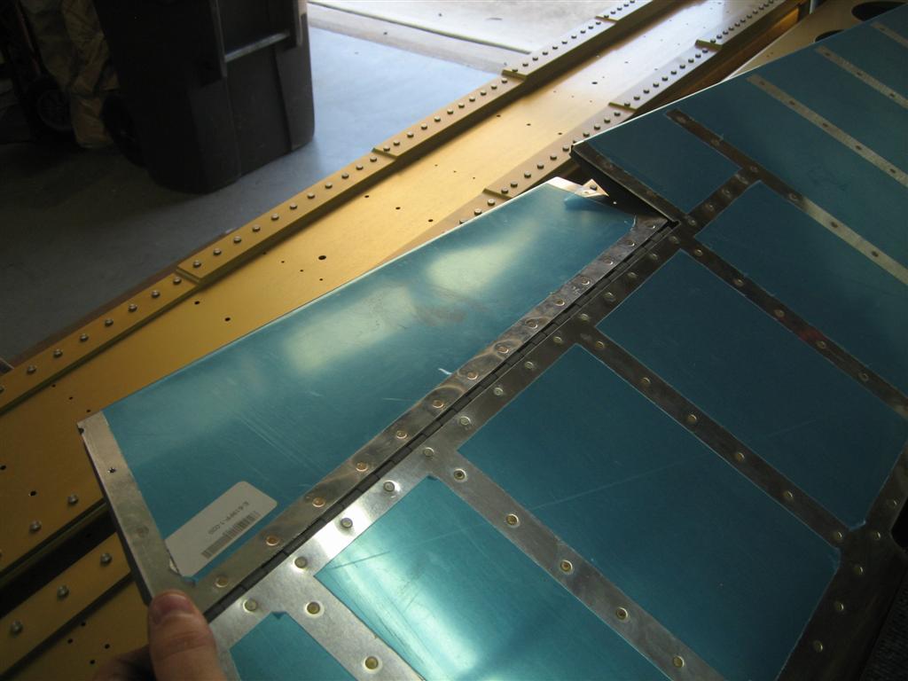
Over the last couple months, I've been eyeing various landing and taxi light setups, trying to figure out what I want to do for my airplane.

I"m not super keen on the leading edge landing/taxi light setup right now, so I want to focus on putting all the lights in the wingtips.

There is a Van's wingtip landing light kit that puts two MR16 sized bulbs in each wingtip. Supposedly, you can aim one set forward for landing (also recognition) lights, and aim the other set down for taxi.

I've read on the forums that people haven't been too thrilled with this setup using the standard 35W and 50W halogens that van's provides. Something about not getting enough light on the centerline of the aircraft, where you need it for landing.

I have also read, however, that with the MR16 HID upgrades from somewhere like www.planelights.com or duckworksav.com, there is plenty of light to go around.

Sweet. I'll go with those. (This is the same as Mike Bullock's setup, except instead of both sets being 50W, I'll probably use one set of 50W HIDs for landing, and use a 35W (pronounced “less expensive”) for taxi lights.

But then we come to wig-wag. I think wig-wag (pulsing lights) for the landing lights is a requirement safety wise, so I am planning on incorporating a wig-wag circuit into my landing lights.

I could just wire them in parallel, so you turn the landing lights on, and either wig-wag them or not depending on wig-wag switch position, but because these are going to be HID bulbs, one needs to warm the bulbs up before pulsing. (I've read that 25 seconds was used previously on HID flashing circuits, so I'm going to use 30 seconds for now, but I may bump that up based on a crude bulb temperature test I may set up in the future.)

Procedurally, I could just wait 30 seconds after turning the landing lights on before turning on the other switch, pulsing them, but who can remember that 100% of the time? 30 seconds is just about the time it takes between turning the lights on for takeoff and liftoff. This is not the right time to be reaching down for another switch.

I'd rather flip both switches ON, and have them automatically warm up before starting to pulse.

Enter xevision. They have a multiple-hundred-dollar HID flasher box that will work great for this application.

Except I'm an engineer, and I love a good problem to solve, and I don't have hundreds of dollars laying around.

Enter Microsoft Visio and B&C. Using Bob N's Low Cost Wing Wag Alternative document (page 2.0) as a starting point, I drew up a concept for a landing and wig-wag circuit with a delay timer (haven't figured out the timer circuit yet, but it's a relay trigger, so I'm going to simulate it with a switch for now).

Keep in mind, I could combine the functions into a 2-10 switch (similar to page 3.0 of the wig-wag document), but then I couldn't use the switch-breaker I'm planning to use in place of the regular switch I have depicted. Maybe this circuit is a good candidate for an inline fuse…I'll sort that out later.

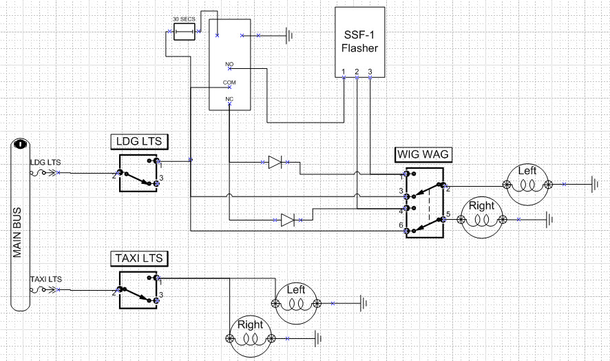
Anyway, here's the circuit for now (since I am a wiring novice, I'll have to figure out how to connect 5 wires to one switch terminal later…I know you can't just bolt them all on there.)
<h2emstrong>SEPARATE SWITCHES (see below for single switch diagrams)</strong/em/h2>
Oh, and I've shown the HID lights here as just normal lights. You get the idea, though.

UPDATE: After testing, I realized I need diodes in here on the flasher side of the 2-3 switch near the NC part of the relay to isolate the two lights. I'll try to draw them in.


Both switches OFF.
wigwagproposal-off3.jpg


+14V will come in to the left, and the lights will be connected to the center terminals of the 2-3 switch in the picture. the fast-on connector at the top of the picture will eventually be connected to a timer circuit that will close the relay (top left) after 30 seconds.

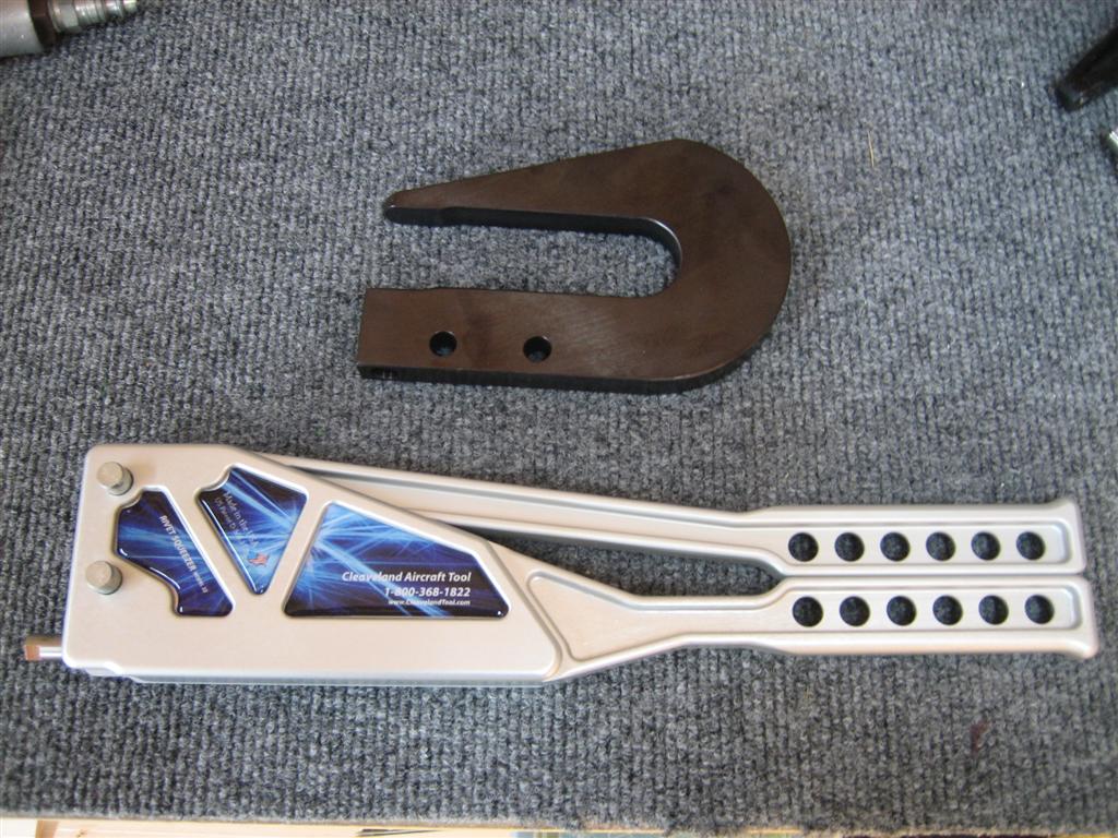
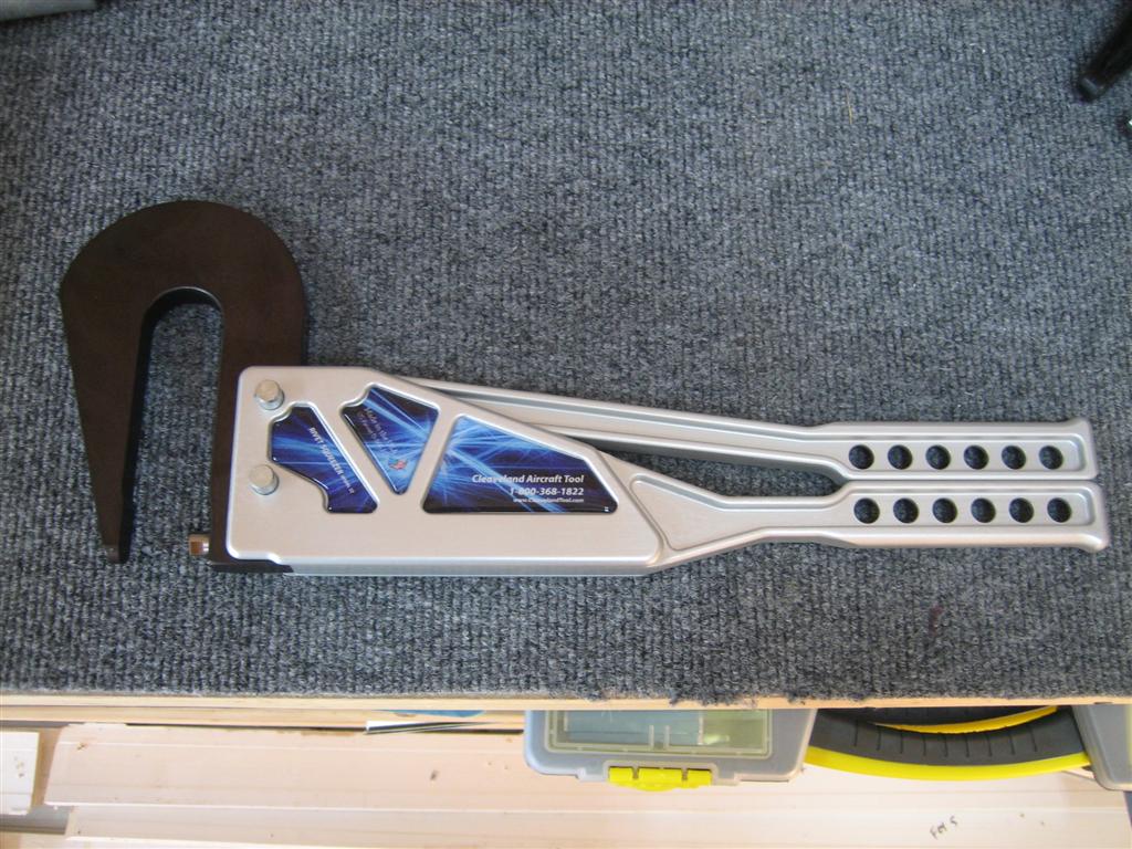
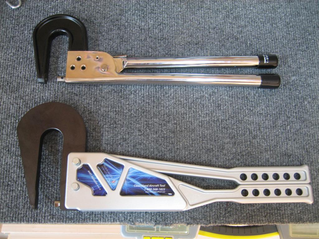
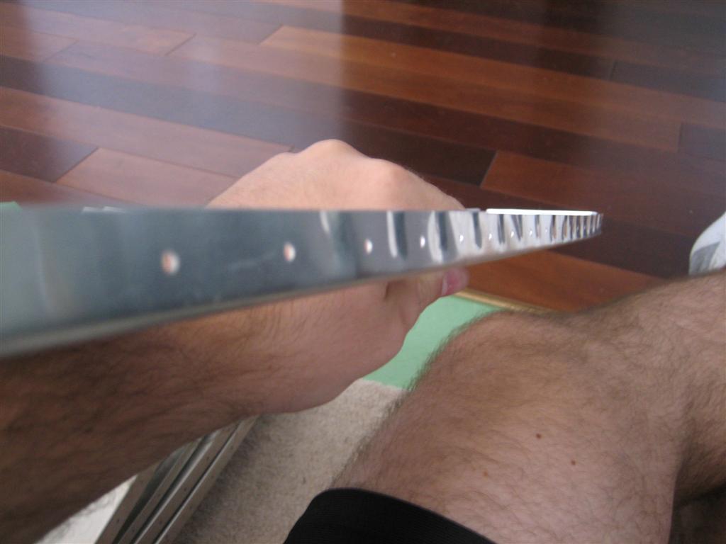
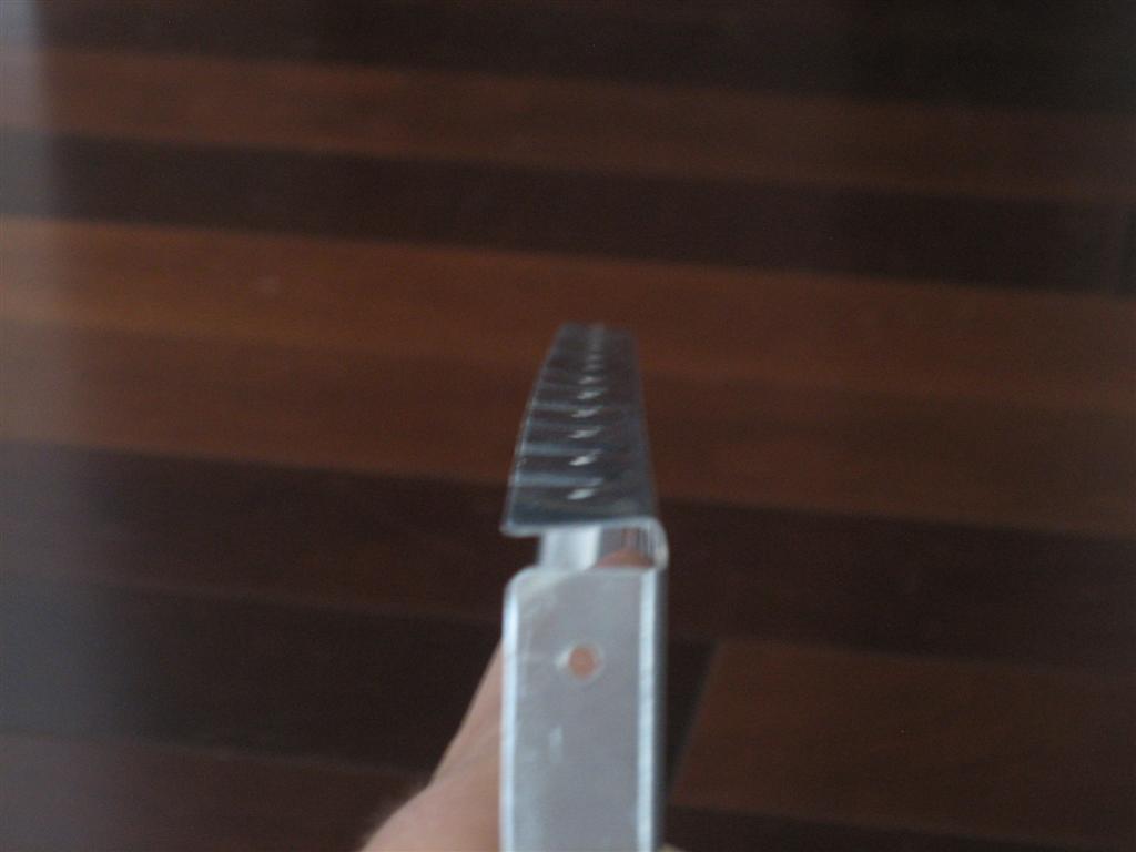
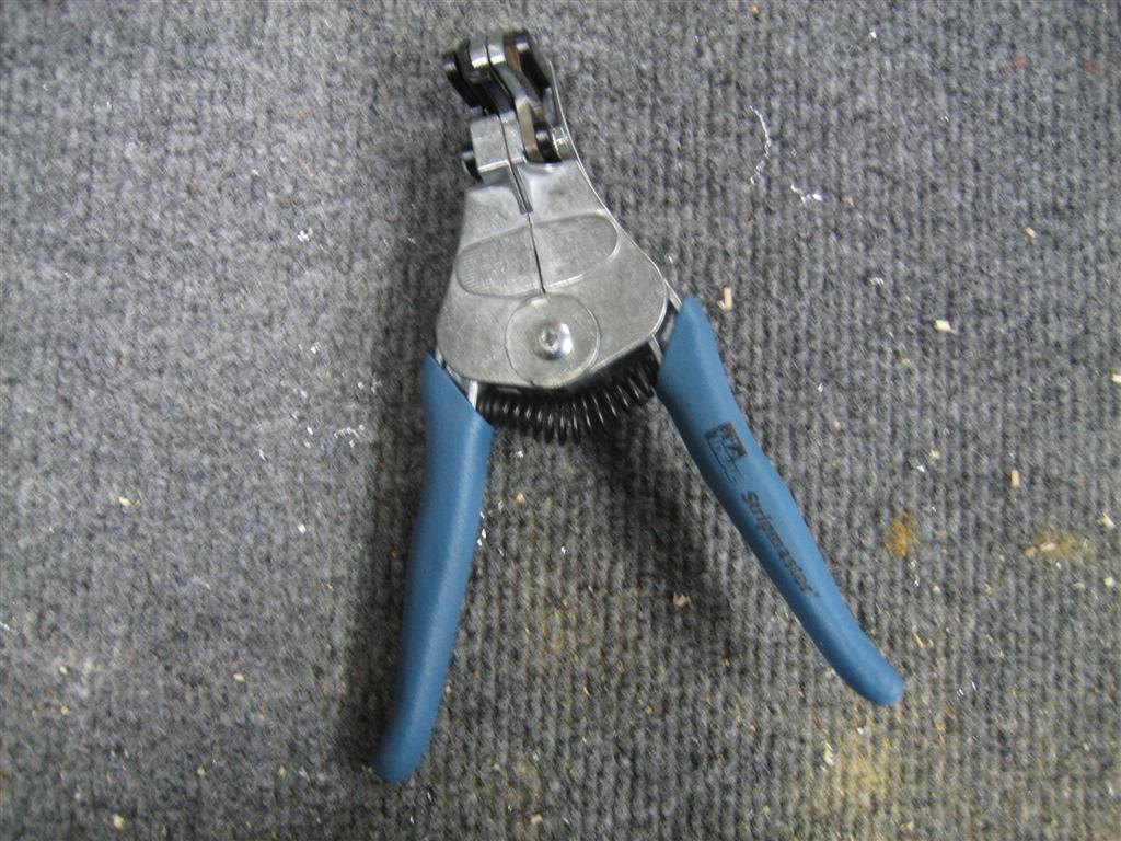
It was too late to start hooking stuff up. Now. Back to the tools. I ran off to Lowe's (after considering buying these things on eBay...no, they need to be sharp, and Lowe's has the name brand one I want), and bought the STRIPMASTER.


Seriously. That's the name you come up with?
20101017-001-large.jpg


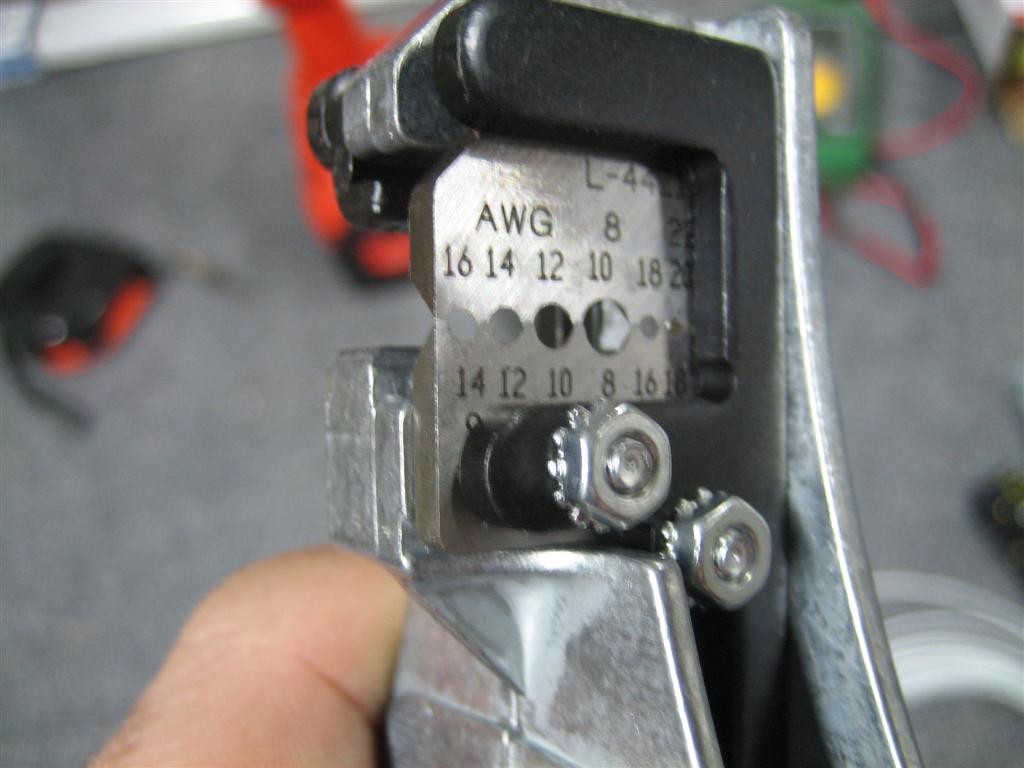
A closeup of the important bits.
20101017-003-large.jpg


This is instead of about 60 seconds worth of stupid tool-knife-stupid tool-hurt hand-knife again-stupid tool just to strip one end of one wire.

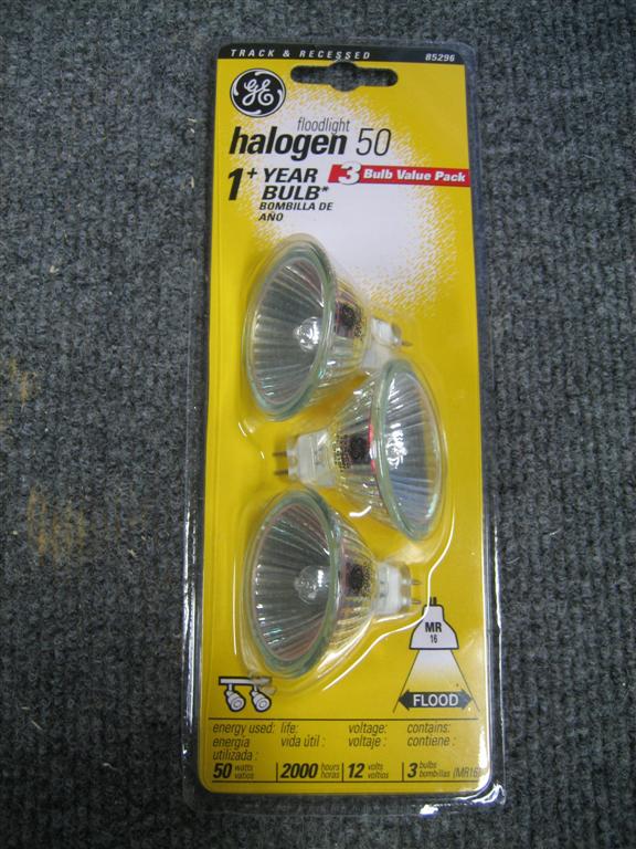
Okay, let's find some lights and start pushing electrons around!


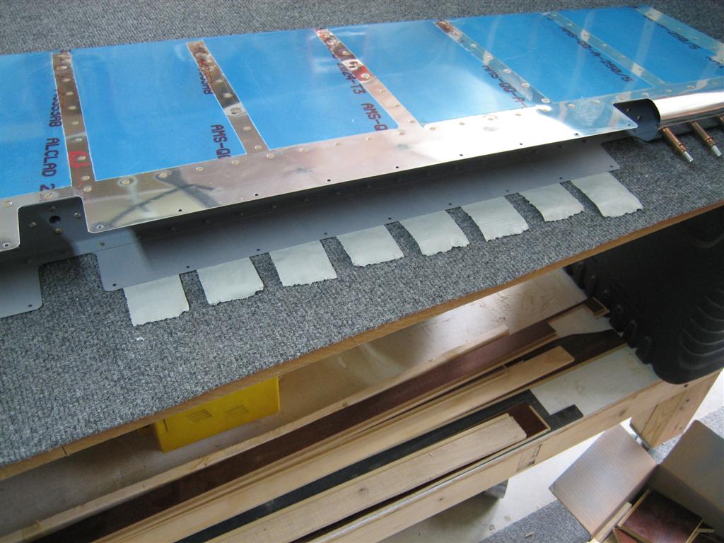
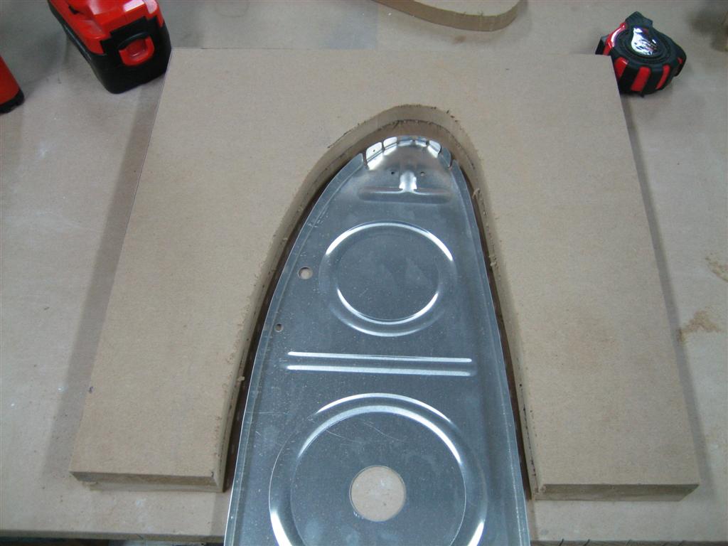
These will do. 12V, 50W. (Enough for a spare for this little experiment.)
20101017-009-large.jpg


Oh, and the wood is so you don't start melting the nice carpet you've purchased for the workbench top. Ask me how I knew to do this.
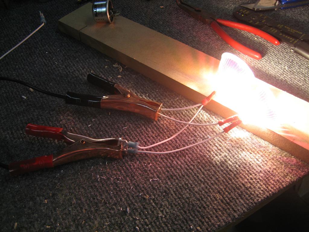

Wuhoo! It's alive!
20101017-011-large.jpg


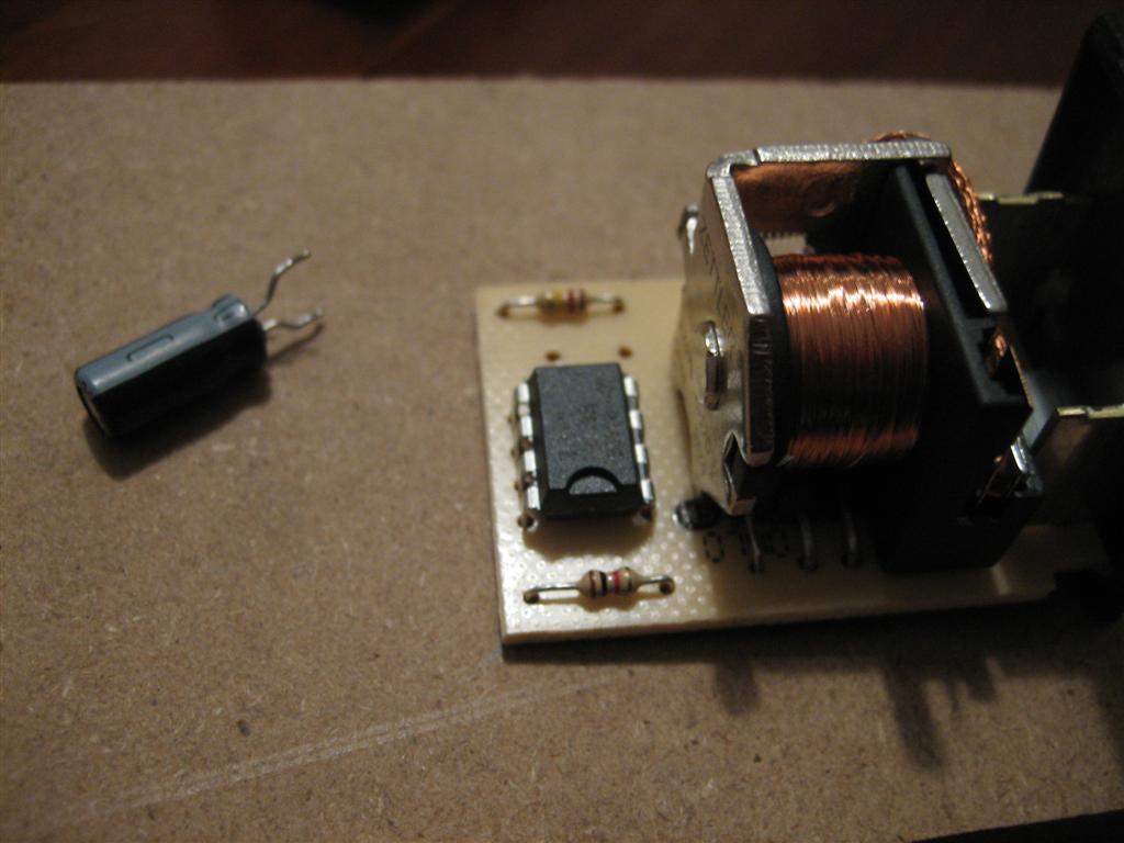
Okay, let's hook up my circuit.

This is LDG ON and WIGWAG OFF.


Sweet. Electrons are still flowing.
20101017-010-large.jpg


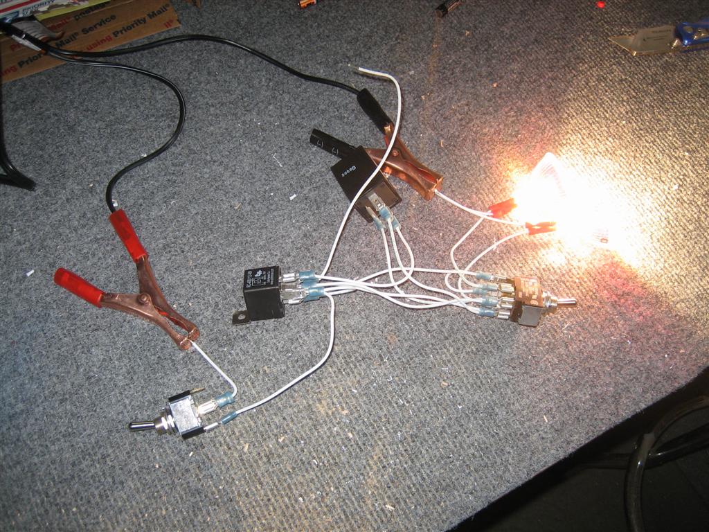
But. This is where bad stuff starting happening.

I threw the WIGWAG switch to ON and then used the simulated timer circuit to close the relay. Nothing happened (lights stayed on).

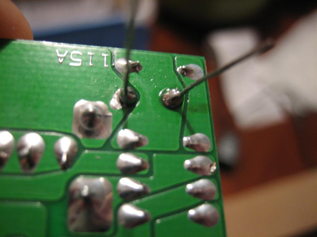
After a little more investigation, I figured out that both the normally open (NO) and normally closed (NC) contacts were getting +14V all the time. Tha'ts not good. (I knew I needed some diodes or something. I'll investigate further seperately.)

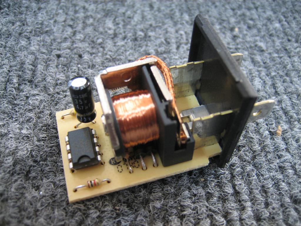
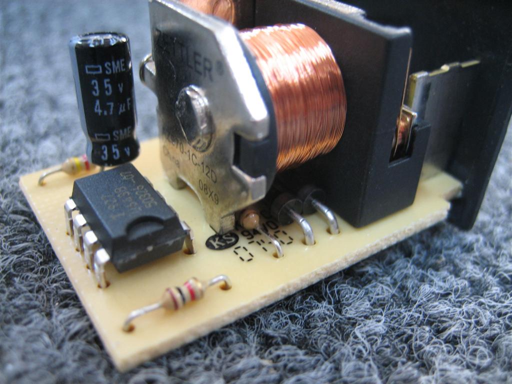
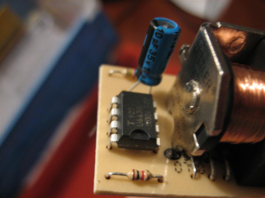
During the investigation, I wanted to make sure that everything works as advertised.

It's making a weird buzzing noise, and the first light comes on, then the second one starts to come on, but it doesn't really finish a singe cycle. I'll have to email the aeroelectric list about it and see what they say.

Since I didn't get that huge satisfaction of a completely working circuit, I grabbed an automotive flasher I had on the shelf.

It's the wrong flash pattern, and it won't work with alternating lights, but it's still cool.

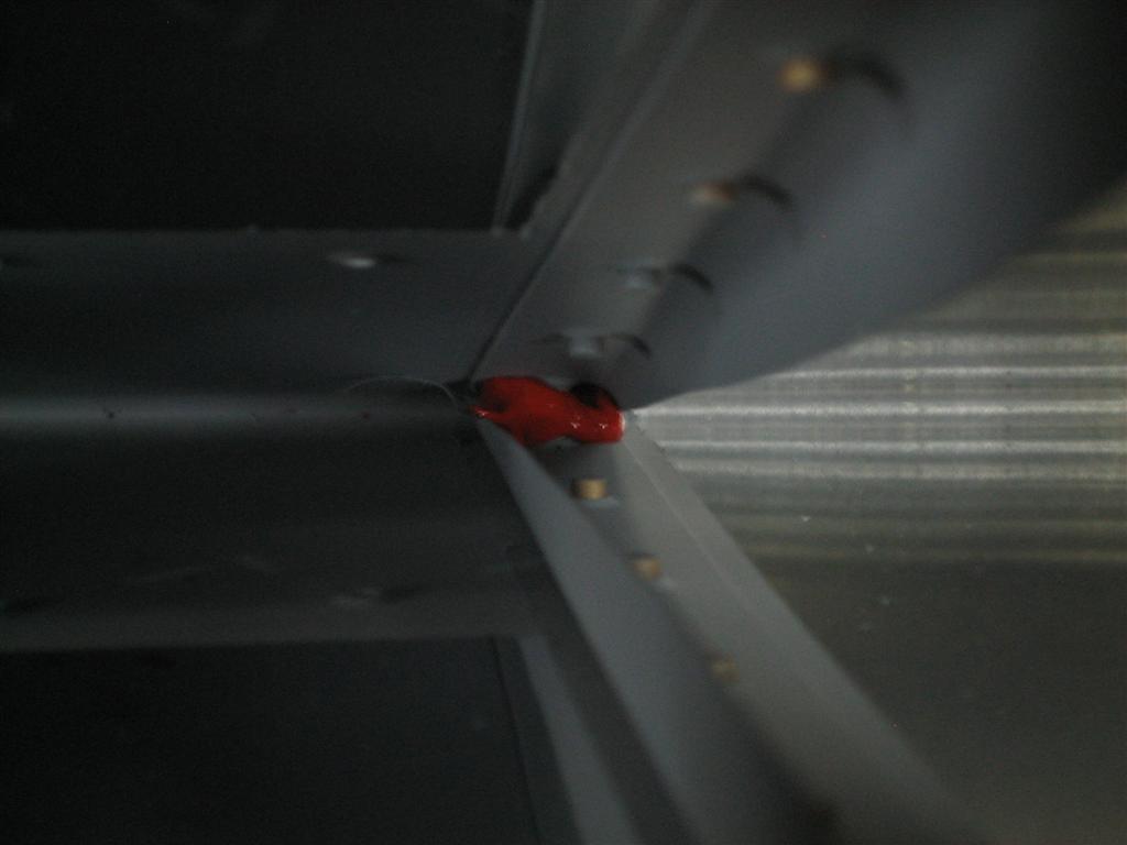
Finally, I bypassed the B&C flasher and checked the relay operation.

First, I turn on the lights. Then, I turn on the wigwag, and the lights stay constant. Third, I'll close the relay so current flows through the flasher (although since it's not hooked up, the lights should turn on.) Let's see what happens.

Wuhoo, my one electrical engineering class in college has paid off!

This was about an hour's worth of work, and since it's ultimately for the build, I'm going to count it as R&D time.

1.0 hours.

Oh, and the next day, I hooked just the wig wag portion up to my car battery, and it worked (I wonder what's going on with my power supply...).
wpvideo h02JJyop]

It's a little fast for me. I wonder if there is a way to slow it down.
Next
 
Post Title: FINISHED DEVINYLING WING SKINS!
Link to Post
Tue, 19 Oct 2010 02:00:49 +0000
Next

WUHUOOOOOOOOOOOOOOOOOOOOOOOOOOOOOOOOOOOOOOO!

(Not that I don't like devinyling...)

No really, it's kind of mindless, easy time-passing.

The real reason this is a win is that it is really the last thing (except for all of the leading edge, aileron, and flap skins) I can devinyl in the airplane room before needing to buckle down, finish up the floors, and really get started on the wings.


I think this is the right upper outboard skin, skeleton side.
20101018-001-large.jpg


And the other side.
20101018-002-large.jpg


Once I really get going on the other side, I need to catch the left main spar up to where the right is, build the left rear spar, and then do the rib prep trick. Then, I'll build a wing stand and start the fun parts (Ha! They're all fun parts!)

0.5 hours.
Next
 
Post Title: Tank Attach Nutplates, Left Lower Spar Flange
Link to Post
Fri, 22 Oct 2010 01:00:25 +0000
Prev | Next

With the girlfriend gone for the night, I managed to clean up all of the electrical stuff I had out messing around with my wig-wag experiment, and pulled the left spar out of the box. Here it is, in all of it's golden glory.
Golden Glory!
20101021-001-large.jpg


First step is to countersink the tank (and access plate) nutplate attach holes. First, you have to run a #40 drill through the holes or else the countersink pilot won't even fit in the hole. Here's one of my first countersinks on the left spar.
I went back and cleaned this one up after testing with a AN426AD3-11 rivet (-11 because it's easier to get back out while testing countersinks...it's so long you can just push it back out from the back.)
20101021-002-large.jpg

These countersinks are a little better. (The one on the right is a tad deep, but should be okay because these are just nutplate attach holes.)
20101021-004-large.jpg


I left the door to the house open so the pups could come out to visit.
Hey guys (Jack and Ginger).
20101021-012-large.jpg


Hey Andrew, how about one of those artsy shots down the spar after countersinking the nutplate attach holes?
Sure, here you go.
20101021-014-large.jpg


Then, I pulled the K1100-08 nutplates out for the tank attach holes and the K1000-06 nutplates out for the access plate holes, then clecoed one side in, and put the required rivet (AN426AD3-4) in the holes.

Where's my squeezer?
It's right there on the table, dummy.
20101021-016-large.jpg

Other side done. (Repeated 41 more times.)
20101021-020-large.jpg


Under the hood, things look good. I still like this new Cleveland main squeeze much better than my economy squeezer.
Pretty shop heads.
20101021-023-large.jpg

Down the row.
20101021-024-large.jpg
 
I then laid the spar down and saw this guy.
Yikes.
20101021-025-large.jpg

Whoa. Scary.
20101021-026-large.jpg


After a little internet research, I think I've figured out he (actually she due to her size) is a red-back. I'm going to keep looking though. I don't want it to be a red-back.

1.0 hour. 84 rivets.
Prev | Next
 
Post Title: Tank Attach Nutplates, Left Upper Spar Flange
Link to Post
Sat, 23 Oct 2010 21:00:41 +0000
Prev | Next

After getting a ton of housework done, I managed a quick half hour in the garage to finish up the nutplates on the left spar.

I took some pictures, but they are just like the ones from the previous post, so I'll be short with the descriptions.


Countersinking.
20101023-001-large.jpg


I found it a little quicker (and less tiring on the drilling arm) to do 4 at a time. I'd countersink four sets of holes for the nutplate attach rivets, then cleco one side of a K1100-08 nutplate in, squeeze the rivet, and then take out the cleco and rivet the other side in. Then move on to the next four.

I'm sure it didn't actually save me any time, but for some reason it seemed quicker.


Just squeezed the first four rivets on this flange.
20101023-002-large.jpg


Nice looking shop heads, if I do say so myself.
20101023-003-large.jpg


Another angle, I guess?
20101023-004-large.jpg


Remove the cleco.
20101023-005-large.jpg


Put in the other rivet (man, I was really camera happy today...)
20101023-006-large.jpg


Everything was going great until the VERY LAST RIVET.
sigh]


For some reason I lifted up the squeezer as I set the rivet.
20101023-009-large.jpg


Another angle (except it's the same angle). Sorry.
20101023-010-large.jpg


After successfully drilling the rivet out. I was left with a crooked nutplate. Hmm.


Problem solving time!
20101023-012-large.jpg


I didn't have a clamp small enough to hold the nutplate in place while I reset the rivet, so I grabbed one of the #8 screws (forgot the part number, sorry), and screwed it in gently.
 
Wuhoo! I think this is going to work!
20101023-013-large.jpg


(Screwed in gently) because I hadn't countersunk yet. This worked great.
20101023-014-large.jpg


See, I told you it worked great.
20101023-015-large.jpg


Last, but not least, I squeezed the AN426AD3-6 rivets for the K1000-4 nutplates near the spar root.


Flush side...
20101023-016-large.jpg


Nutplate side.
20101023-017-large.jpg


64 Rivets, ONE drilled out in 0.5 hours.

Oh, and then I went for a run with the pups. (And by run, I mean rollerblade.)
wpvideo 7gOkMGQN]
Prev | Next
 
Post Title: Hacking the Wig Wag Flasher
Link to Post
Sun, 07 Nov 2010 20:40:25 +0000
Prev | Next

It was a great weekend. I didn't get much airplane stuff done, but I did wake up to this:


Awesome.
20101107-006-large.jpg


There's the capacitor, on the upper left.
20101107-008-large.jpg


I didn't think this would be a simple 555 timer circuit, but it is.


Let's see, this is a 4.7 µF capacitor. I'll go by a 10µF and 20µF to try out.
20101107-009-large.jpg


Oh yeah, almost forgot. A few weeks back I bought an Ideal Crimpmaster tool on eBay for $20. It was the coaxial one, so I had to buy the dies elsewhere. I got them for $20, too, from Stanley.


Here are the dies for insulated terminals.
20101107-010-large.jpg


I fired up my (new) soldering gun and heated up the solder on the back of the board enough to pull the old capacitor out.


Sweet. That was easier than I thought it would be.
20101107-014-large.jpg


Here's the 10µF capacitor installed.
20101107-015-large.jpg


Not great, but not terrible either.
20101107-016-large.jpg


So, I put the thing back together and fired it up. I'm calling this a huge success.

Half an hour of wondrous electron-pushing work.
Prev | Next
 
Post Title: Countersunk Left Main Spar, Drilled Left Rear Spar
Link to Post
Sat, 13 Nov 2010 19:50:16 +0000
Prev | Next

Well, I managed to motivate myself out into the garage a little this weekend.

I only have a few more steps on the left main spar, and the the left rear spar, before I really need to get my butt in gear with the rib deburring and finally build a wing stand.

Today, I focused on countersinking the screw holes for the tank attachment.

I broke out my trusty digital calipers, zeroed them out, and dialed in .312."
Sorry for the blurry picture.
20101113-001-large.jpg


So, with microstop countersink cage on the front of my drill, I got to work. Here are the smaller countersinks for the #6 inspection plate attach screws on the bottom flange of the left spar.
Pretty countersinks.
20101113-002-large.jpg


Then, I moved up to the 0.370" countersinks for the larger #8 tank attach holes.
Looking good.
20101113-003-large.jpg


Somewhere in here I flipped the spar over and finished all the countersinking on the upper flange of the left spar.
Sweet.
20101113-005-large.jpg


After the countersinking, I scrounged up the left rear spar and corresponding doubler plates.
Left Rear Spar, reinforcement fork, and doublers.
20101113-008-large.jpg


Per the plans, I grabbed the W-707E and aligned it 50 3/4" from the outboard edge of the rear spar.
I promise it is right at 50 3/4". I think the paralax make it look off.
20101113-009-large.jpg


W-707F is laterally aligned with the outboard edge of the rear spar channel.
W-707F is clamped and ready to matchdrill.
20101113-010-large.jpg


Here's W-707E, ready to drill.
After drilling one #30 hole.
20101113-011-large.jpg

All done.
20101113-012-large.jpg
 
Then, I moved outboard to W-707F.
Before matchdrilling.
20101113-013-large.jpg

All done.
20101113-014-large.jpg

I call this the forest of clecos.
20101113-015-large.jpg


I moved inboard and matchdrilled all of the reinforcement fork holes.
A lot of drilling.
20101113-016-large.jpg


I pulled the doubler plates and reinforcement fork off and set them aside.
I still need to drill out the aileron pushtube bracket hole.
20101113-017-large.jpg

Reinforcement fork pulled off.
20101113-018-large.jpg


Next up, deburr all parts, along with finishing any last minute tasks like dimpling where I can't reach later, then prep for priming, prime, and rivet the rear spar together.

1.5 hours.
Prev | Next
 
Post Title: Prepping and Priming Some Rear Spar Components
Link to Post
Sat, 20 Nov 2010 22:21:30 +0000
Prev | Next

Oh man, I'm furious. I just spent some time doing a huge writeup for this post, and when I clicked, "Post", it deleted all of my text.

Grrr.

I'll try to rewrite it, but it is going to have a little bit of an annoying tone.

Anyway, I managed to get out in the shop today for a little. I had previously gotten all of the doubler plates and reinforcement forks matchdrilled to the spar, so today was all about prepping and priming.

Here's W-707F, which sits on the back side of the left spar. I've deburred and scuffed it; all I need to do now is dimpled the outboard holes in preparation for attaching it to the spar and outboardmost rib.
I love scuffed parts. They hide my fingerprints.
20101120-001-large.jpg


Here's W-707E, which is the doubler plate that sits on the aft side of the rear spar, right in the middle. I've marked the cutout for the aileron push tube. Where's that step drill?
Yup, here you can see my fingerprints.
20101120-002-large.jpg


I started looking around for my stepdrill. I spent good money on that stepdrill, but I couldn't find it anywhere. On the workbench, under the workbench, on the floor, in some other shelves. I thought maybe I put it in some other tool's case, so I got out the dremel tool, multifunction tool, jig saw, circular saw, etc. Nothing.

I even accused the girlfriend of selling it on the black market to fund an bottle of Opus One. She insisted that while she thought about it, she didn't.

I remember putting it in this old small cabinet of drawers (that my dad gave me when I graduated college...thanks, dad!). I spent about 30 minutes just pulling out each one of these drawers, looking for my step-drill. Grrr.

After continuing to work on the airplane (angrily) for another 30 minutes, I finally found it when I came back to the drawers and opened them with my other hand. Apparently my sausage fingers (they're not, I promise...I'm just mad) blocked my view of the stepdrill, which was right behind the lip of the VERY FIRST DRAWER.

Ugh.

Anyway. Back to the rear spar. This is the forward side of the left spar, outboard end. I've deburred the edges of the whole spar, and now I'm deburring all of the holes I drilled.
I always scuff the areas where there are holes I've drilled and deburred. Helps me keep the "did I do this already" time to a minimum.
20101120-003-large.jpg


Oh yeah, I managed to get a couple parts primed today. Like riveting, I always feel like it is a productive day if I can prime some things.
You can also see my primer of choice, Napa 7220.
20101120-004-large.jpg


Here's the other side of those pieces (after plenty of drying time).
I like priming.
20101120-005-large.jpg


Back to the spar, more deburring holes and scuffing.
I'll finish scuffing the whole spar when I get closer to priming.
20101120-006-large.jpg


This is the middle of the rear spar, around the aileron pushtube hole. More deburring and scuffing.
Jeesh, there are fingerprints everywhere.
20101120-007-large.jpg


Finally, I brought the two primed parts back inside.
Primed parts on the workbench always means we're getting close to riveting. Wuhoo!
20101120-008-large.jpg


After this was about when I finally found my step-drill. I was too angry at myself to keep going, so I headed inside to some grilled chicken, jasmine rice, and creamed corn. Mmmm.

1.5 hours
Prev | Next
 
Back
Top