We plan our RV10 to be IFR; essentially G3X/GTN 650 plus a small Dynon. We think we want I alternator plus 2 batteries, 1 start and 1 domestic, something akin to what boats have. The idea would be to set up the avionics before engine start, but protected from spikes/surge. But we are still thinking how to achieve this in practice. Has anyone got a system like this? I have a Dynon D6 in a Eurofox and it says you can have it on through engine start, but I assume you cannot take such liberties with Garmin stuff. Also, is the standard Vans voltage regulator OK? We know someone who allegedly got a big over-volt and destroyed most of his Avionics, but I am not clear how that would happen.

Van's Air Force
You are using an out of date browser. It may not display this or other websites correctly.
You should upgrade or use an alternative browser.
You should upgrade or use an alternative browser.
Electrical system Architecture
- Thread starter colestopp
- Start date

Mike S
Senior Curmudgeon
I have a similar system to what you are describing, but two alternators and two batteries.
My main circuit has the 60A alternator and large battery PC 925, while the aux circuit has a 8A alternator, and a PC 680 battery.
All of my radio stack, and the EFIS systems are powered from a buss supplied from the PC 680-----breakers and switches etc as needed---------and the rest of the aircraft is powered from the buss off the PC925.
There is a large Schottky Diode that connects the two buss's together, and allows current to flow into the aux buss from the main, but not the reverse.
System has been flawless for 4 1/2 years 210 hours.
Sorry, but I do not have any drawings I can either post or email------
Bluelabel
Well Known Member
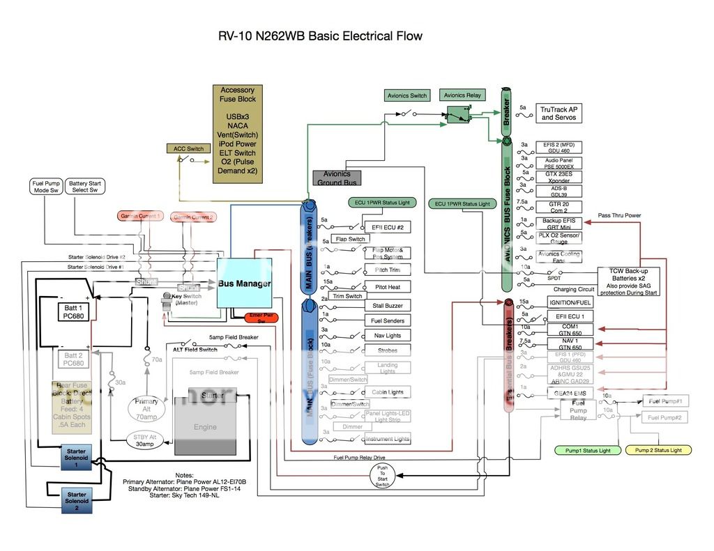
Without getting into a longwinded thing on this topic, I wanted the same solution. I chose to go with 2 alternators and 2 batteries. We are doing Daul EFII Ignition AND Fuel Injection, full IFR platform, so I was looking for as much redundancy as I could... After all, it's me and my family in the plane.... The two batteries are essentially isolated from each other except during start up and where they can be summed via the Bus manager if one battery is week. It also provides bus power to electronics during start up. In addition, since we already spec'd in the TCW Backup batteries, I spoke with Bob and he said they will ALSO provide sag protection for whatever components are wired to it during start up. That way I can have one screen and my GTN 650 up and running to input a flight plan etc, prior to start up.
Here's a copy of my Schematic... It's just the basic power flow, not every single wire or the gauge of wire. I have to warn you, I'm NOT and electrical engineer. I put this together, and had it throughly picked apart by Robert at EFII and Doug at Stein Air. We made several revisions and this version got a resounding thumbs up from both. So, take that for what it is.
I believe this is the 5th revision.... the only thing I still might move is where the shunts are going... But that really comes down to personal pref based on my research as to what you want to monitor. People do it differently for different reasons... there's a whole thread on just that.

Last edited:
Aeroelectric Connection
You need a copy of Bob Nuckoll's Aeroelectric Connection. Lots of information, lots of architecture drawings in the appendix.
https://matronics.com/aeroelectric/Catalog/pub/pub.html
You need a copy of Bob Nuckoll's Aeroelectric Connection. Lots of information, lots of architecture drawings in the appendix.
https://matronics.com/aeroelectric/Catalog/pub/pub.html
Bluelabel
Well Known Member
You need a copy of Bob Nuckoll's Aeroelectric Connection. Lots of information, lots of architecture drawings in the appendix.
https://matronics.com/aeroelectric/Catalog/pub/pub.html
I agree, read it more than once, part of the reason I opted for mostly fuses instead of CBs... saves money, saves weight and you shouldn't be resetting them in the air anyway.....
BillL
Well Known Member
We plan our RV10 to be IFR; essentially G3X/GTN 650 plus a small Dynon. We think we want I alternator plus 2 batteries, 1 start and 1 domestic, something akin to what boats have. The idea would be to set up the avionics before engine start, but protected from spikes/surge. But we are still thinking how to achieve this in practice. Has anyone got a system like this? I have a Dynon D6 in a Eurofox and it says you can have it on through engine start, but I assume you cannot take such liberties with Garmin stuff. Also, is the standard Vans voltage regulator OK? We know someone who allegedly got a big over-volt and destroyed most of his Avionics, but I am not clear how that would happen.
I worked with SteinAir for my panel. I was told the Garmin may drop out when starting and have to set up again, so they suggested a backup battery that kicks in on start or alternator failure, just for avionics.
The starting battery is still there too. PC680.
I am not worried about a surge or over voltage on start-up. In operation, my plane power has OV protection internally.
I think all bases are covered. YMMV, so look at your power demands for all the conditions and failure modes.
2 alternators, one battery and a TCW device to hold the voltage up while cranking is probably a more maintainable set-up. Bob Nuckolls has some very good suggestions. If you are keen on an IFR clearance i would suggest you don't buy any electrical / avionic equipment until the LAA has published their IFR TLs. Buy a Plane Power or B&C alternator, with proper OV protection. With the relevant, quite straight forward, precautions any avionic equipment can be left on during start.
Pete
Pete
Last edited:
majuro15
Well Known Member
John, looking at your schematic, I see that there could be a high amp continuous load on your main bus. (Consider IFR at night, landing so pitot heat, landing lights, etc). The bus manager manual says the max continuous output on the main bus is 40 amps. Did you get any feedback from EFII on that? The essintial bus being max 30 amps is pretty easy. I also realize that actual amp draw is lower that circuit protection ratings, but not sure what the variance is.
Stephen
I have a diagram for an E-bus system I designed for my plane and which is also installed on a friends Rocket. It is a reliable and simple system for one alternator and two batteries. No electronics, three busses (main, avionics and essential), one diode and two switches.
Send me an E-mail address and I will send a copy of the Rocket diagram
George, RV8, 1475 hours
Nukeflyboy
Well Known Member
Electrical System Architecture
My system is very similar to Mike Starkey's, except I use a bus tie solenoid as specified in Nuckoll's book. There are many ways to design your system and I doubt that any 2 are alike.
The important question to ask yourself is do you plan to use electronic ignition? If so, will it require external power? If the answer is yes to both, then you will need some redundancy, particularly if you run with 2 EI systems. Two batteries and two alternators is the gold standard.
I have a G3X and GTN and they will crash if on the same bus as your starter. It won't hurt them, but your engine will run for a minute with no engine monitor as the G3X reboots. There are other products out there to temporarily hold up the voltage on the avionics during cranking if you don't want to go with two batteries.
The Dynon D-6 has an internal battery that will keep it humming even in the event of a total electrical failure of both busses. Great redundancy there.
The important concept to learn is FMEA: failure modes and effects analysis. This will find the weak point in your design (every design has a weak point) and determine if it is acceptable for your flying profile, and resale.
To help keep the G3X from dropping out during start you should make use of the GAD 27 low voltage protection voltage stabilizer system. A TCW battery tied to the master bus will also provide power to keep the systems up during start, and these batteries are relatively low cost.

