What's new
Van's Air Force

Don't miss anything! Register now for full access to the definitive RV support community.

Cooling air inlet plugs

Bob Axsom

Well Known Member
I've gone through two iterations of inlet plug development and I'm starting into the third. In the first phase I made 24 cooling air inlet plug plates of 1/4" balsa and flew them to determine what restriction gave me the best speed without exceeding 400F CHT on any cylinder. I started with 3 plates glued together as the base and added one plate for each successive test flight. The results indicated that 1.75" restriction in each inlet for my unique cooling air system was best. In the second phase I tried different leading edge shapes and found that a shape that kept the air out of the inlet as well as restricting the openings was best. I have started phase three today by making a clay leading edge on the balsawood plug in the right inlet (photos below). I will fiberglass this one through a process I used to make my intersection fairings then start on the left one. If you see anything wrong let me know but unless it is really bad I will take this to completion in a test flight. These plugs are to be removable and I intend to use them for racing only at this point.

Bob Axsom


dvc00001es8.jpg

dvc00002qn4.jpg

dvc00003gm1.jpg
 
Last edited:
Very cool Bob - I salute your inventiveness and persistence! You truly have the spirit of experimentation!

Paul
 
The results are inconclusive

When I did the original test I was using the US Air Race Handicap Procedure to determine TAS under a standard set of conditions. At that time the numbers were:

base3 = 171.1
base3+1 = 171.7
base3+2 = 170.5
base3+4 = 172.2
base3+5 = 171.9
base3+6 = 170.6

These numbers are invalid because the test method is not compatible with gusty cross wind or vertical wind conditions. With the rear baffle hole plate mod I just completed the required cooling air mass appears to have been reduced and the TAS was found the be 174.3 kts using the USAR & NTPS test methods together. It is probable that the 1.75" dimension is not optimum and there may be no resulting increase in speed at all. However, I'm going to try it and find out. It is a high risk task as far as performance increase is concerned. If it doesn't pay off the plugs will go into the sacrifices to the God of Speed pile.

Bob Axsom
 
Might I suggest

Bob.

Might I suggest a tweak to your learnings before you get too far down a "glued" in road.

There are a couple of NASA studies around "chin scoops" that you should probably go read. I believe your best approach will be one where there is a smooth transition between the bell of the spinner and the eldge of the inlet of the cowl duct.

Also I believe that a round opening with a sharpe edge will be more aerodynamic than a "D" shaped opening. Something ala the Sam James Cowl for example.

*IF* you feel the need to bring the hole closed from the inside out as you are showing in your "clay work". I'd suggest you do it by going to a larger diameter spinner and then allowing that shape to form the smooth transition into the cowl duct.

Some of the speed mods that Andy Chiavetta gets out of Daryl Greenemeyers Lancair legacy had to do with creating large round, sharpe openings for the cowling, but smoothing the "laminar" flow from the spinner into those openings. Also the work that the guys did to Jeff Lo's Biplane's cowling were based on similar findings.

I'd hate for you to much up a perfectly good cowling, just to find that the better solution was to do something similar to the above.

I'm no expert around this, but I did stay at a holiday inn express last night :).

Excellent work and continue to share. I'll got back into my cave now.
 
Thanks Alan

Yeah this looks pretty crude but I'm tied into some requirements that are shaping my direction. The mod I am starting on now is kind of evolutionary but the supporting development base is very weak - I'm hanging out in the wind really. The mod is completely reversible in that the plugs will be held in place by the cowl screws, much longer than normal of course. I do not want to create any damage to the cowl or the paint so this has to be done very carefully. If I run into trouble with the right plug only that side will be affected as sad as that will be. The Wichita 300 and the AirVenture Cup start in 3 weeks so there is some urgency in the picture. Any gain will be good. I will probably try to do something better next year but I have to move with what I have for now. Thanks again for you observations and ideas.

Bob Axsom
 
First Layup pulled - looks good

In the first photo you can see the right plug has been pulled from the cowl, the balsawood base separated from the fiberglass and the clay has been dug out of the fiberglass cavities. The left plug is still in the cowl in the second photo. Since the photos were taken the left plug was pulled separated and cleaned. Since that time both fiberglas units have been bunded to the balsawood bases with epoxy and stabilized by several 3/32" round head rivets inserted with epoxy as pin. The pins will become obscure as additional layers are added.

Bob Axsom

dvc00001ew0.jpg

dvc00002ym8.jpg
 
Question on drag

It looks like the plugs are somewhat blunt as opposed to sloping. Would that increase drag and create turbulent airflow? Just a bubba thinking out loud. What does a Sam James cowl opening look like?
 
Looking good Bob - I'm trying to understand the little "valley" in the plugs (looking down on them, how they protrude forward next to the spinner and forward on the outboard edge, but then you have the dip aft. Looks cool, but my education in flows is a long time ago....Hope you see some speed after all your work!

Paul
 
The leading edge

Here is a summary of how I reached the current leading edge shape.

Phase 1 - When I first started working on the idea of plugging the inlets as part of the evolving effort to reduce cooling drag the leading edge was determined by the height of the opening and the distance from the front of the inlets to the front of the cowl. This was quite blunt. On my cowl the leading edge of the left cooling air inlet is farther back from the leading edge of the cowl behind the spinner than the right indicating that there is some side thrust in the design. Thus the right side plug is more blunt than the left. However, testing with increments of 1/4" width closure of the openings from the inboard edge indicated there was some increase in speed to be had from this form of reduction in cooling air inlet size. There is also an increase in CHT. After the plugs width reached 1.75" the speed appeared to drop but the CHTs continued to increase. I interpreted this to indicate the parasitic drag of the plugs were exceeding the reduction in cooling drag due to the reduction in air mass flow through the cowl after the plug width exceeded 1.75" and the CHTs were getting into the 400 F range. Further study at a much later time with the NTPS spreadsheet indicates that the nice curve correlating the number of 1/4" test plug plates with airspeed indicated by the USAR Handicap Procedure was illegitimate but I chose to press on anyway using the 1.75" plug width.

Phase 2 - I glued seven of the test plates together for each inlet to obtain the desired plug width then I extended the maximum protrusion of the leading edge by gluing on seven crescent shaped extensions. I could see by looking at the light contact mark on the rear spinner plate that the blades rotate all the way back to this plate at high pitch. The extensions could extend past the front of the cowl and the back of the spinner but I had to leave room for the propeller blade trailing edge when rotated to high pitch. The maximum protrusion of the leading edge of the plug near the hub is aft of the front of the spinner back plate with the crank shaft pushed in and the outboard edge of the plug tapers back to allow for the broadening of the propeller blade as it extends outward. The first test was made with the lightly tapered leading edge and the last one had the leading edge tapered sharply back into the cooling air inlet opening. The ~straight plug was faster than the sharply tapered plug. That is all I concluded from this phase.

Phase 3 - This is the current phase and other than construction the leading edge is the important difference. The inboard leading edge extends as far forward as it is safe to go without a prop shaft extension. Then it dips back smoothly to through a depression then returns forward to form a smooth protruding lip isolating the inlet from the air inboard of the opening. I hope this will result in only the air directly in front of the opening, entering the cowl.

This is definitely a "work in process" and no performance improvement may come of it. I suspect I will have to install the rear baffle hole cover plate to hold down the CHT of cylinder #3 at least. We shall see. It will take a week or more for me to finish these plugs.

Bob Axsom
 
Cool Bob - Thanks for the insight into the process!

We could use more of your kind of engineer back in the program these days BTW....)

Paul
 
Thanks Paul

You have no idea how good that makes me feel. I see Dawn is launching soon. I know how the people are going to bed late, sleeping little, waking up early and bonding into a tightly knit team in anticipation of the launch after years of development, reviews and operational planning and simulations. There is nothing else like it. I hope the young folks realize it and are aspiring to the exploration of space. I played my small part as well as I could and I loved every agonizing minute of it.

Bob Axsom

Ironflight said:
Cool Bob - Thanks for the insight into the process!

We could use more of your kind of engineer back in the program these days BTW....)

Paul
 
Last edited:
Nearing completion

I have a 24 hour cure cycle to complete, sand, add another layer on the leading edge, wait 24 hours, sand, fill, sand, redrill and countersink the mounting holes and it will be ready to test. We will be out of town for a few days beginning Friday so the test flight will probably be around the 4th of July.

Bob Axsom

dvc00001hn8.jpg
 
EZ-Poxy

The part A material is clear but the 24 hour hardner is a very dark amber color (100:44 mix by weight). It is epoxy from Aircraft Spruce.

Bob Axsom
 
Bob Axsom said:
The part A material is clear but the 24 hour hardner is a very dark amber color (100:44 mix by weight). It is epoxy from Aircraft Spruce.

Bob Axsom
Hmm, I have some sitting around in my hanger, maybe I'll give it a try, you like how it works?
 
Bob,

Could you explain to this non-aerodynamic type what the thought process is regarding the unusual forward facing shape of the plugs? There appears to be two "humps", one near the spinner and one near the cowl inlet. I'm interested to know what this should do.

Thanks!

Thomas

edit - oops! I must have missed your prior post ... never mind :)
 
Caution on the forward protrusion

Just in case someone else tries this:

1 - The top view photo of the clay molding is the early shape which is still similar but I did trim them back after the photograph to provide more clearance from the trailing edge of the prop at high pitch. That is explained earlier in this thread.

2 - The forward protrusion not only has to be clear of the prop trailing edge but the spinner as well in its worst side displacement. My test in Phase 2 had no problem but the temptation to get closer and conform to the contour of the spinner could be a big problem.

Bob Axsom
 
Bob Axsom said:
When I did the original test I was using the US Air Race Handicap Procedure to determine TAS under a standard set of conditions. At that time the numbers were:

base3 = 171.1
base3+1 = 171.7
base3+2 = 170.5
base3+4 = 172.2
base3+5 = 171.9
base3+6 = 170.6

These numbers are invalid because the test method is not compatible with gusty cross wind or vertical wind conditions. With the rear baffle hole plate mod I just completed the required cooling air mass appears to have been reduced and the TAS was found the be 174.3 kts using the USAR & NTPS test methods together. It is probable that the 1.75" dimension is not optimum and there may be no resulting increase in speed at all. However, I'm going to try it and find out. It is a high risk task as far as performance increase is concerned. If it doesn't pay off the plugs will go into the sacrifices to the God of Speed pile.

Bob Axsom

Don't give up too quick, Bob. I need to know if all the work is worth it as I have a major challenge getting my machine to move out a bit more than it does.

I've about ruled out the James cowl as the answer primarily due to cost. It is good looking but the end result may not be worth the money so why get rid of a perfectly good Vans cowl. What you are doing is much less costly and the same affect can be achieved. I read a comment by Van on the round inlet - it was done because it is easier to calculate the area of inlet rather than going oblong. :)

My first task is to do something about the hole chopped into the cowl below the spinner for the oil cooler. It needs a contoured scoop similar to the upper inlets. It will take some time, but by using the technology you are, it can be done.

Thanks for posting the pictures.
 
Bob: Just a note from someone who isn't even flying yet (F1 Rocket in work which I am hoping to fly to Sun n Fun next year). I really appreciate the effort you put in to share your experiments with the community. Whenever I see your name associated with a post, I always stop and read it.

Thanks for your efforts! If you ever get a Rocket, I'll have to put your email address on speed dial!!!

Warm regards,

Lee Logan
F1 kit #160 (Sun n Fun next year---are you listening in, Danny??!)
 
logansc said:
Bob: Just a note from someone who isn't even flying yet (F1 Rocket in work which I am hoping to fly to Sun n Fun next year). I really appreciate the effort you put in to share your experiments with the community. Whenever I see your name associated with a post, I always stop and read it.

Thanks for your efforts! If you ever get a Rocket, I'll have to put your email address on speed dial!!!

Warm regards,

Lee Logan
F1 kit #160 (Sun n Fun next year---are you listening in, Danny??!)
Ditto for me.

With only 135 HP on tap, I want to play with my -9 after it start flying to see what I can do to keep up with the 180 HP -7's and -8's.
 
Looks Great Bob

You've definitely done a nice job of shaping to keep the boundary layer off the spinner out of the inlet as well as limiting the bluntness in that area.

The one problem area I notice is the quick expansion behind your new inlet lip. I see that you need to get the glass back to the existing cowl since that's where it attaches, but the flow may separate here. It is hard to judge though since we don't know what angle the flow is really at in this area.
 
Please expand

keen9a said:
The one problem area I notice is the quick expansion behind your new inlet lip. I see that you need to get the glass back to the existing cowl since that's where it attaches, but the flow may separate here. It is hard to judge though since we don't know what angle the flow is really at in this area.

Please expand this information so I can address your concern on the plugs themselves. I test flew for safety only this evening and there is some cleanup to do as well as adding another layer of fiberglass of the front. You technical insight and comments are greatly appreciated.

The photo below shows the configuration as flown. I made an effort to cuff the inboard end of the inlet and fair it into the cowl with the clay and layed up the fiberglass girectly over the clay cowl and balsawood plugs but I have not trimmed the outer edge yet to make their outlines nearly the same. I'm flying to St. Louis tomorrow (I hope) so I removed them after the flight. During the full range of flight operations there is no interference (rubbing) between the plugs and the prop or spinner. Even though I did not remove the cowl and install the rear baffle hole cover plates the before the flight, the CHTs did not go above 400F (382 F was the highest I saw). Because of local weather I could not get up to my 6,000 ft density test altitude. I don't know if I would have any way because I wanted to make sure there was no interference between the plugs, spinner and prop before I got too far away from homebase. I want to get the front view profile established and add a thin anti-chaffing strip on the plugs where they contact the cowl. There is work to be done yet but I feel it is safe to proceed.

Bob Axsom

dvc00001rr6.jpg
 
Last edited:
Question on cowl hinge pins

Bob,

I have another question for you. What do your hinge pins look like underneath the covers you've fabricated? Are they bent for pulling or do they just have a blunt end? How about the condition of the cowling in that area? I'm thinking about how to get an acceptable finish on mine and the idea of not being overly concerned about finish, optimizing the ability to remove and install the hinge pins and then covering it with a fitting as you have is very appealing. Would it be possible to have you take a couple of pictures with the pin covers removed so I could see what it looks like underneath?

thanks much
 
The curve around the lip, and then the ramp back to the original cowl between the arrows is where you might have an issue. I would test first, but then if the performance isn't as hoped, make the curvature more gentle in that area.

81366721.jpg
 
the hinge pins

trib said:
Bob,

I have another question for you. What do your hinge pins look like underneath the covers you've fabricated? Are they bent for pulling or do they just have a blunt end? How about the condition of the cowling in that area? I'm thinking about how to get an acceptable finish on mine and the idea of not being overly concerned about finish, optimizing the ability to remove and install the hinge pins and then covering it with a fitting as you have is very appealing. Would it be possible to have you take a couple of pictures with the pin covers removed so I could see what it looks like underneath?

thanks much

The ends of my hinge pins are looped to one side, the top, so the loop only interferes with the upper cowl. I cut a "D" shaped opening in the upper cowl that fits the loop nicely. Then I insert the side hinge pins in the cowl I push them in place then rotate the loop into the opening. The covers are made from 0.016" 2024 T3 aluminum. There are three mounting screws, two on the outside anf one on the inside of the cooling air inlet. Platenuts are riveted inside the cowl at the six locations and the cowl holes are countersunk. The mountintg holes on the two plates are dimpled. There are several benefits of this atangement: 1 - ease of implementation 2- the cowl separation loads are applied the the 0.016 alumimum in tension instead of the hinge 3 - the screw and end of hinge pin are eliminated from the external cowl surface, 4 - the gap between the cowl haves at the leading edge is eliminated.
I will try to remember to photograph it for you after I get back to Arkansas on Tuesday.

Bob Axsom
 
Thanks for that input

keen9a said:
The curve around the lip, and then the ramp back to the original cowl between the arrows is where you might have an issue. I would test first, but then if the performance isn't as hoped, make the curvature more gentle in that area.

I will do exactly that, test first to see what I have then consider the radius options if it is not satisfactory.

Thanks for that good input.

Bob Axsom
 
Status

7-3-07 returned from St. Louis today and started preparing the plane for a test flight with the plugs in place. Removed the cowl and instaled the race plates to cover the holes in the rear baffle. Weather permitting I'll get it back together and fly tomorrow. In the mean time one fellow wanted to see the horizontal cowl hinge pins under the leading edge cowl split covers. Here is a photo of the right side with the cover removed (including wax and bug residue:

dvc00002ig1.jpg


Bob Axsom
 
Last edited:
Production opportunity?

Bob Axsom said:
keen9a said:
The curve around the lip, and then the ramp back to the original cowl between the arrows is where you might have an issue. I would test first, but then if the performance isn't as hoped, make the curvature more gentle in that area.

I will do exactly that, test first to see what I have then consider the radius options if it is not satisfactory.

Thanks for that good input.

Bob Axsom

Bob,
Those look very nice. I had been contemplating building something similar for different reasons---maintaining CHT in very cold weather flying(have since moved to warmer weather). It seems you may have something that could be put into production for those who live in colder climes?
Mark
 
redbeardmark said:
Bob,
Those look very nice. I had been contemplating building something similar for different reasons---maintaining CHT in very cold weather flying(have since moved to warmer weather). It seems you may have something that could be put into production for those who live in colder climes?
Mark

Anyone that is interested, feel free to do what you like with this info. I have no interest in producing these plugs.

Bob Axsom
 
Test flight completed ... so-so

The clouds finally broke up enough this evening for me to squeeze in a test flight at 6,000ft density altitude - the standard I have used for all my testing (per USAR Handicap Procedure). I trimmed the plugs and added teflon anti-chafe tape on the cowl mating surfaces. Photos follow:

dvc00005rr2.jpg

dvc00006up8.jpg


The temperature at 6,000ft pressure altitude was 19C so the test was flown at 4,400 ft pressure atlitude for the 6,000 ft. density altitude per the US Air Race Handicap Procedure. 2,720 RPM, Oil Temp 200, Oil Pressure 80, Manifold Pressure 25.5, CHT/EGT = 1-333/1251, 2=399/1318, 3=397/1306, 4=348/1266.

TAS = 173.8 kts per NTPS spread sheet

This is 0.5 kt slower that the last test which had no plugs but the rear baffle plates were installed for that test (and this one) and well over 2 kts were gained in that configuration. The CHTs are higher in this configuration than in the Plugs out configuration. The oil temperature was also 10 degrees hotter in today's test compared to the previous one. On the face of it there is no reason for me to keep the plugs but I will for a while at least. I have the inner cowl seperated into 3 isolated zones and zone 3 has my interest at this point. All of the air coming through the baffle is dumped into this zone and I have provided only a tiny vent (1/4"x7") at the top of the standard cowl outlet for it. With all of the baffle holes blocked except the oil cooler only the oil cooler air is going in there. The pressure should be reduced and the vent may be adequate but what if the main speed gain of the previous mod was due to the reduced pressure - it would seem that there may be more speed there if the pressure was reduced further. Also, since less air mass is entering the cowl as evidence by the higher CHTs then it seems that the cooling air outlet in the cowl could be reduced without reducing the airplane's speed. Since cowl zone 2 and 3 outlets are the are separate parts of the standard cowl outlet, increasing the zone 3 share might increase the airplane speed. The size of the zone 3 outlet is controlled by stacking washers on screws that attach the zone 3 outlet panel to the bottom of the firewall flange (platenuts on the flange). More to think about.

Bob Axsom
 
Last edited:
Also...

May drill a pressure relief hole in the leading edge depression and add a fiberglass web across the depression.

Bob Axsom
 
Small mod

I drilled a #40 hole from the front face of the plugs all the way through the blocks then applied a layer of fiberglass with a web over the depression in the leading edge. As you can see there is a void under the new layer but it is not straight across - there is some sag. This will take 24 hours to cure then I will test fly it.The leading edge will bw slightly less blunt and the radius of the side lip into the inlet will be slightly greater but not much. I have to hold off with the cowl zone 3 vent increase until I have tested this mod.

Bob Axsom

dvc00008zx4.jpg
 
Bob,

If you really want to learn whether a particular mod is worthwhile, I strongly recommend to check the speed with that mod on more than one flight. There are a number of reasons why you may measure a different speed on different flights, so you need to average results from several flights to really know the performance. Right now, as far as I can tell, you are flying each configuration on one flight, then making a decision about whether the latest mod helped or hurt. There is a good chance that your current approach is leading you to make some erroneous conclusions. This is OK if the whole point is simply to have an excuse to do mods and fly the plane. But if you really want to maximize the speed, you need to get credible data on which to draw conclusions.

I want to see you succeed in maximizing the performance of your RV.
 
Kevin You Are Right as Usual

The right way to do it is several flights and average the results probably given no special reason exists to not include any particular flight from the set. Time and money are real life problems I have to deal with so compromises are being made. I have a 300 mile race out of Wichita a week from Monday so I am really squeezed for time to get the best speed I can for that. Right now I will Fall back to the "plugs out", "baffle hole cover plates in" unless I get someting greater than 174.3 kts with the current plug mod. I also need to vary the amount of cowl outlet area allocated to the air coming through the cylinder cooling fins into my cowl zone 2 and the air coming through the oil cooler into my cowl zone 3 and fly test for effect. Less than a week after that I have to fly the AirVenture Cup race from Dayton to Oshkosh with very little opportunity for fine tuning anything. After that the honey do list is going to have to be worked. My best time for significant work will be in the winter and spring. Hopefully I won't throw any gems in the trash bin in my rush but I appreciate your observation and will try to exercise a little more caution.

Note: I have flown so many of these tests that they are not independent events anymore. The norm is fairly clear and when something does improve the performance significantly it is recognizable.

Bob Axsom
 
Last edited:
KEEP TESTING AND TESTING!!!!!!!!!!

Hey Bob,
Keep seeking and working with what your doing, I?ve got my thumbs up for you as I?ve been there and done the trial and error thing with testing and trying this and that. I understand the time thing, many hours, weeks, months of testing, family time and money.

To date with everything I?ve done with the cooling / speed mods on my RV-6 have been trial and error. What I post or share is at everyone?s own risk and I take no responsibility. I?m only sharing what works on my grocery getter RV

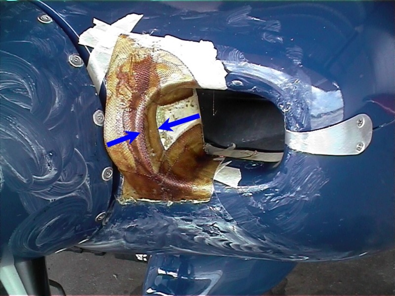
An update with my setup: Cowl inlets are 2.750? round each with around a 5-7 degree diffuser angle that extend into the plenum for about 8? average. Left inlet is longer than the right because of the cylinder spacing. The work inside the plenum is very important!

July 4th , 2007 I took a short flight in 100F air on the ground to Dodge City, KS from my base airport of 2,500ft. After takeoff, I ran at 24.5? and 2,550 RPM till I reached 11,500 ft in about 6 minutes+. After around the 9,000 ft mark I was making 21.5? MAP. Fuel mixture was kept at 125F rich of peek on the climb out. Indicated airspeed was kept at 125-130 mph from takeoff too 11,500ft. The air temp at 11,500ft was 65F. Yikes,,,, not that cool, but better than 100F on the ground.

The highest CHT was 365F on climb out and the oil temp peeked at 190F when I leveled off at 11,500ft. This is like hanging it on the prop with Spam cam cruise speeds in cruise and working the engine.

At cruise speed after a few minutes, the CHT's were in the 325F range at 11,500ft with 65F air.

I?m not trying to brag or whatever, but it takes much work to get an RV to keep within these limits. I?m running a true 10:50 comp ratio Angle Valve IO-360A1B6 making 200HP++ with Slick Mags set at 20 degrees of advance,,,,, no electronic ignition etc.?and as most people know this engine can sometimes be a tuff cookie to stay in the green range at times.

Attached are a couple of pictures of my diffusers/cowl inlets. Not posted are pictures of the inside of the plenum, as I have none. Kind of hard to take pictures inside of a dark cavern where a bear lives while he?s hibernating?.LOL

Keep testing and testing within reason. I?ll be at Oshkosh this year and I?ll have the cowling off my ?6 if anyone wants to look OK. I have nothing to hide as I?d like to help anyone with cooling problems.

BTW. Humm OK speed gain that I?ve seen between a stock Bernard/James cowling/plenum and my changes are about 3 knots?. Wooooooh. Not much but 3 knots is 3 knots. These test have nothing to do with a stock RV cowl!!! All prior tests many years ago were done with an OEM Barnard////now Sam James stock plenum and cowl. The upper plenum, cowl inlets, lower cowl mods, diverters , diffusers have been changed from the OEM manufacture. What has been done is my design and is altered. Test and try at your own risk. :eek:
dsc07624jw6.jpg
dsc07635qn8.jpg


dsc07629ri4.jpg


dsc07623oa7.jpg


dsc07485pl3.jpg
 
Last edited:
Very Impressive

Very Impressive Alan. 3 kts to the average man on the street may not sound like much but believe me I appreciate how great a 3 kt gain is on an already clean airplane. The engine is very impressive as well. I'm running a stock 180 hp O-360-A1A. It is 6:10 Saturday morning and we get to go to some friend's 60th anniversary party this afternoon to time is a little tight but I thing my latest mod has cured enought to put them on the plane and get a test in before my wife wakes up. See you later and thanks for the information.

Bob Axsom
 
No Test - Fog

Did some rough sanding, added new teflon anti-chafe tape and installed the plugs but the fog is the worst I have seen here. The fit is good and the plugs look good and ready for test but IFR to VRF on top is not a good idea for testing. Hopefully, later.

Bob Axsom
 
Test Complete

Late this afternoon (July 7, 2007) I was able to get my testing done. I flew with the newly modified cooling air inlet plugs in place. Here are the data:

RPM=2,720
MAP=25
Oil Temp 190
Oil Pressure 80
Temp at 6,000 ft pressure altitude 17C
Test flown at 4,600 pressure altitude for 6,000ft density altitude per USAR
CHT/EGT: 1=335/1254, 2=399/1333, 3=400/1300, 4=347/1278
Speed 172.7kts per NTPS spread sheet

This compares unfavorably with the 173.8 kts recorded using the plugs with the deeper depression in the leading edge.

Immediately after this flight test I removed the plugs in 17 minutes and repeated the test but I left the removable baffle plates installed over the holes in the rear baffle. Here are the relevant data:

RPM=2,720
MAP=25
Oil Temp=190
Oil Pressure=80
CHT/EGT: 1=325/1300, 2=378/1368, 3=378/1346, 4=337/1318
Speed 174.7kts per NTPS spread sheet

This is essentially the same speed obtained when I tested the removable baffle cover plate mod with no cooling air inlet plugs on June 21, 2007 (174.3 kts).

I see no evidence that the cooling air inlet plugs I developed for our RV-6A to reduce the air mass flow and thus reduce cooling drag are of any value with regard to speed increase. I have to assume that this is because the drag of the plugs thmselves are greater than the reduced cooling drag. Perhaps with a prop shaft extension and the ability provided to work with the shape more, some improvement is possible but I don't think there is anything there with the standard cowl and simple plugs. I hope this has provided some case study information but for me it is just an interesting experiment that added to my education.

Now I will increase the portion of the cowl outlet allocated to zone 3 and see what that brings.

Bob Axsom
 
Last edited:
Another flop

I added two AN960 washers to the stack on the Cowl zone 3 baffle to give it a 1/8" taller vent.

dvc00002vw8.jpg


The data are:

6,000 ft pressure altitude temp 20C
flew at 4,300 ft pressure altitude for a 6,000 ft density altitude per USAR
RMP=2,720
MAP=25.5
OT=190
OP=80
CHT/EGT: 1=324/1221, 2=375/1304, 3=371/1309, 4=333/1300

Speed 173.6 per NTPS spreadsheet

that is an apparent reduction in speed of ~1kt. I took the washers back out and this is the configuration I'll fly in the Wichita 300 and the AirVenture Cup.

Bob Axsom
 
Last edited:
A further development thought

Assume that the data show by raised CHTs that the air mass flow is decreased by the inlet plugs and the further that the change in shape of the leading edge of the plugs between the inboard lip of the reduced opening and the spinner cause a difference in speed. Is there a leading edge shape that with the existing plug and cowl limitations that would reduce the parasitic drag of the plugs? For example vertical peaks and groves inline with the desired air flow?

Bob Axsom
 
thanks for the pics

Bob,

Thanks a lot for the photos and description of your hinge pin capturing arrangement. This will help on the same for my plane!!
 
Thanks for the flight test work

Bob,

Thank you for posting the pictures, a narrative of the work and the flight test results. I do believe I will leave the primary inlets alone and concentrate on the oil cooling inlet and exit flow for now.
 
Last edited:
That seems reasonable to me

My personal experience says the cowl design is going to be hard to improve upon. I had a nice telephone conversation with Tom Martin of Ontario, Canada this morning and his work with his Rockets has led him to a similar conclusion. He said he was able to pick up some speed with a lot of work and he recommended an article in the August 2003 Sport Aviation that he says is very good. We talked about inlets, cowl flaps and fairings but especially the inlets. I have the set of Sport Aviation on CD and I definitely will study the article - you may find it interesting as well for your work.

Bob Axsom
 
Read the article - Outstanding!

Thank you Tom for telling me about the article "Cool it! Engine Cooling and Drag Reduction". It is written without technical pretense, as if Neal Willford was your neighbor and he didn't have to prove anything to you. He describes every element of the cooling system and gives hard numbers and formulas for you to use in designing or improving your system. I have frozen my configuration for the summer but I will try to improve my airplane's system using this information over the winter. This should be required reading for anyone thinking about improvement of their cooling system and reducing the associated drag. The inlet lip shape and the defuser function and shape are included as well as the interaction of the inlet and outlet on the mass flow. Very good information.

One thing I found a bit disappointing with the EAA Sport Aviation CD for this issue is three figures referenced (4,5, and 6) are not included. Perhaps they were not in the original magazine either because this appears to be an unedited copy. I am going to check with the EAA.

Bob Axsom
 
cowling exits

Bob,
Could the cowling air exit area need an adjustment to make the smaller inlet area work? If you reduce the amount of air in might you need to reduce the exit area to maintain a certain velocity of the air flowing thru?
I am no engineer but isn't the gain related to making the air move through the cowling and exit the cowling at a higher speed? ( Closer to the speed of the slip stream )
Race 34
 
See Neal Willford Article in Sport Aviation Aug. 2003

Tom Martin of Ontario, Canada informed me of the Article in the August 2003 issue of Sport Aviation written by Neal Willford EAA 169108. It is the best I have seen on the subject and it is entitled "Cool It! Engine Cooling And Drag Reduction." I have copies of the NACA reports referenced at the end of the article but his article itself covers our needs completely and goes directly to our installations/systems. My experimentation is not complete but I have to freeze the configuration for now because of the races over the next 10 days and trips that we plan to take over the summer. The plugs I made do reduce the air mass flowing through the system to the minimum level required to maintain the CHTs at or below 400 F with the fixed outlet area. If I reduce the outlet area one would think that the lower cowl pressure would be increased and the differential across the engine would be reduced and the CHTs would rise. It might increase the speed but you may have to increase the inlet area to get the required cooling back. You can probably get this balanced for optimum speed with adequate cooling experimentally but I am trying to get the information associated with the article to get the best starting sizes, see how those compare with what I have and proceed from there. I am sure you are right that the cowl exit needs work and a flap would be great. The NLG really makes implementing a cowl flap (cooling air flow throttle) complex but it can be done. My idea is to have the flap inside the existing cowl outlet and that may require and extension of this part of the cowl to get it in. Another approach would be to change the profile of the cowl aft of the filter airbox and use the section of the cowl itself and the flap between "tunnels" for the exhaust pipes. It requires a lot of thought but it cannot be ignored.

See you at Dayton next week.

Bob Axsom
Race 71
 
Look me up at Oshkosh....

Bob and others,
Look me up at Oshkosh and I'll take the upper cowl off my -6 so you or anyone can see some of the things that I have done with the cowling / plenum. I have small cowl inlets, 2.625" I.D. and a small cowl outlet that are way under VAN's specs and I'm in the 330CHT range on hot days and oil temp is at 185F all of the time. I'll leave my cell phone number on my prop, the EAA paper thing that hangs on it if you or anyone wants to call me or meet up. AJ
 
Back
Top