Captain Avgas
Well Known Member
I'm opting for an IO360 with Precision Silverhawk vertical updraft fuel injection. After a fair bit of research it does appear to me that the best location for me to instal the Floscan 201B fuel flow transducer is either between the mechanical fuel pump and the throttle body, or between the throttle body and the fuel distributor. Either should work well with this type of injection system providing there are no sudden discontinuities either going into or out of the transducer (and it is orientated with wires up).
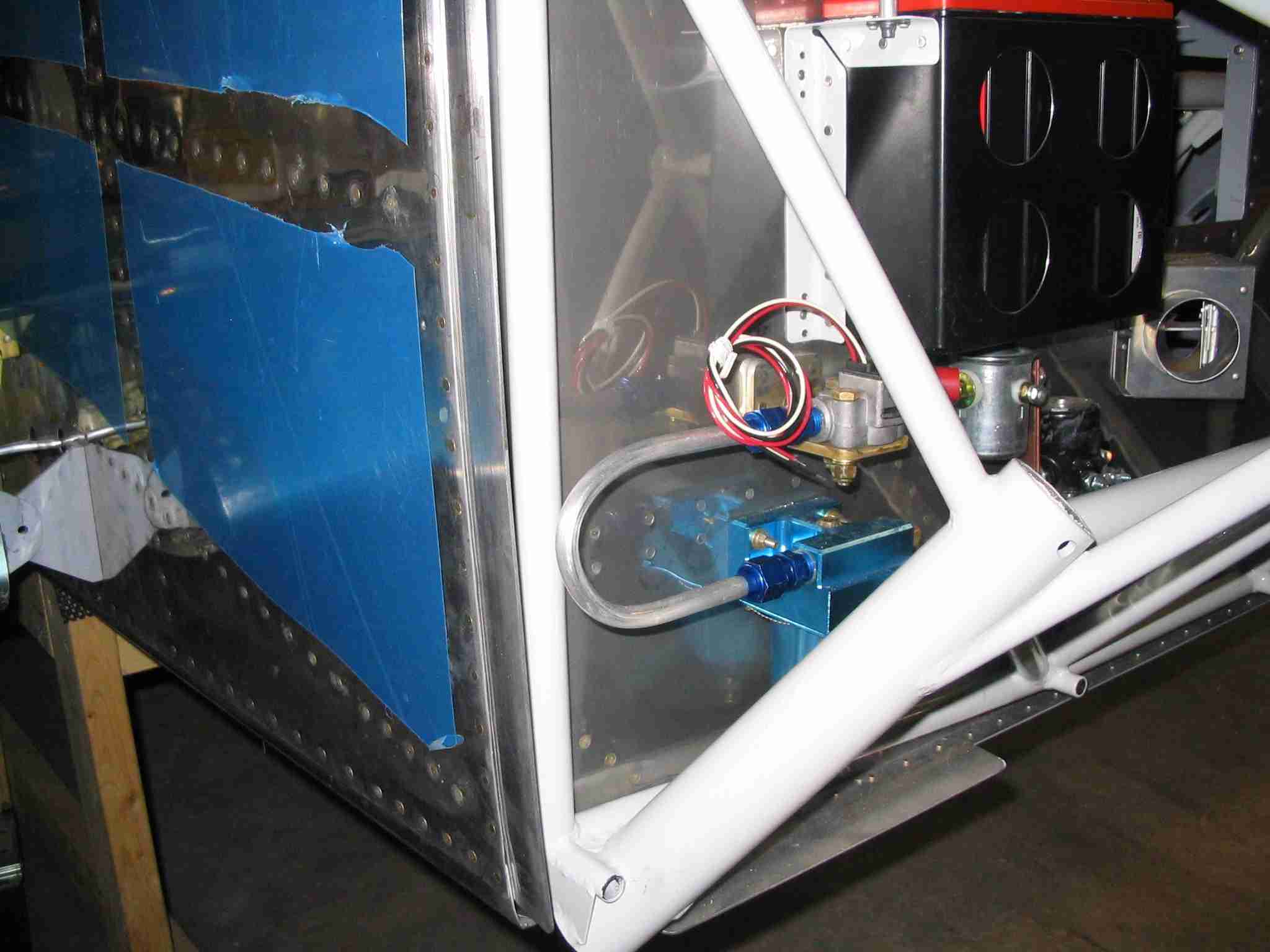
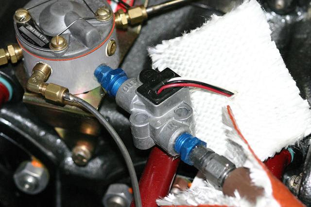
However it seems that there are 3 possible support conditions for the transducer. 1. Installed mid-hose 2. Mounted on the firewall 3. Mounted on the engine.
Does anyone have any pix of their firewall forward transducer mounting. It's one of those things that are very difficult to conceptualise through words so pix would be appreciated (together with comments on success of course).