I did a search on CAN Bus and a few other keywords but didn't find a install/wiring thread, but if there is one, please point me that direction. Here is one thread I found, which helps.
http://www.vansairforce.com/community/showthread.php?t=110252
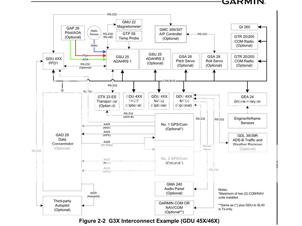
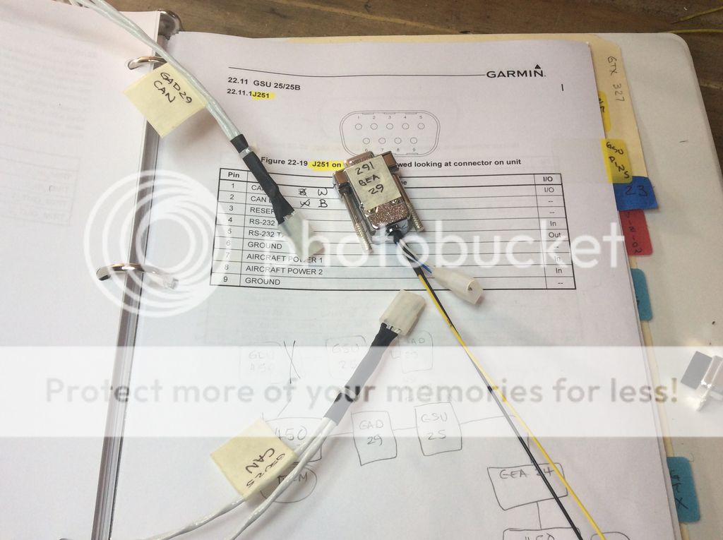
I am working on the wiring portion of my G3X install and would love to see some more examples of the CAN Bus solution people are using. I did see the thread re the can bus and servos and that helped a bit.
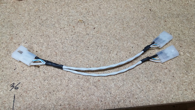
I dont have a problem doing the way I have seen, using solder joints and heat shrink, but I sort of expected to see some recommendations that used a connector. It looks like the signal lines are all nice and neat from point to point using robust connectors and then we get to the CAN bus and just slap that together.
Wouldn't it be useful to at least use pins and sockets and then heat shrink them, so future expansion might only require undoing the heat shrink, and inserting a new device?
Sorry for the ramble, and please don't get me wrong, it is just my impression at this point.
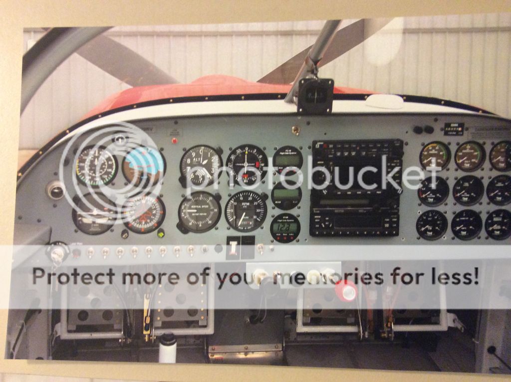
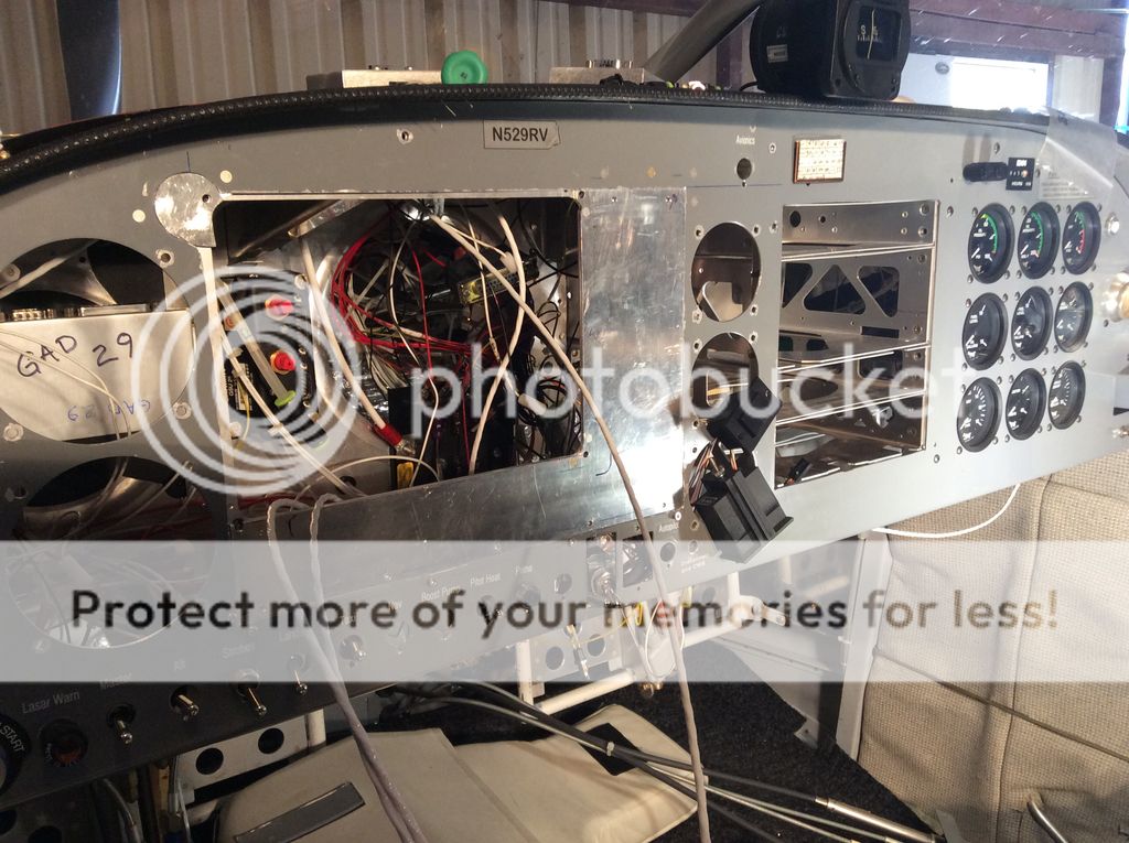
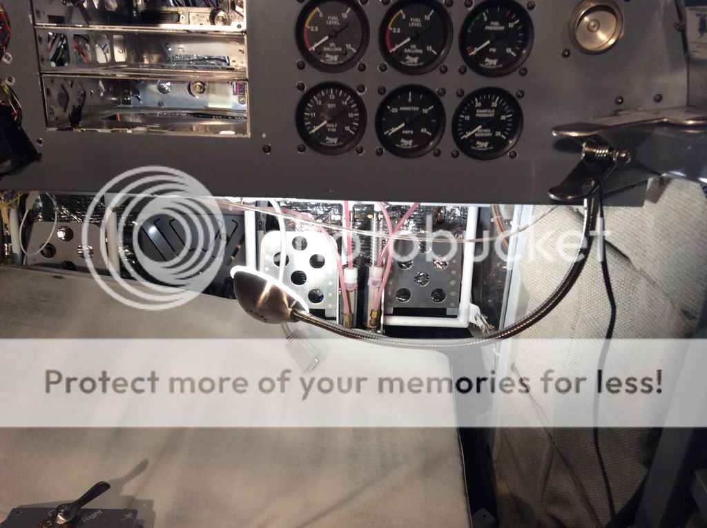
I would really like to see some pictures of this part of the panel wiring.
Jim D
http://www.vansairforce.com/community/showthread.php?t=110252
I am working on the wiring portion of my G3X install and would love to see some more examples of the CAN Bus solution people are using. I did see the thread re the can bus and servos and that helped a bit.
I dont have a problem doing the way I have seen, using solder joints and heat shrink, but I sort of expected to see some recommendations that used a connector. It looks like the signal lines are all nice and neat from point to point using robust connectors and then we get to the CAN bus and just slap that together.
Wouldn't it be useful to at least use pins and sockets and then heat shrink them, so future expansion might only require undoing the heat shrink, and inserting a new device?
Sorry for the ramble, and please don't get me wrong, it is just my impression at this point.
I would really like to see some pictures of this part of the panel wiring.
Jim D
Last edited:
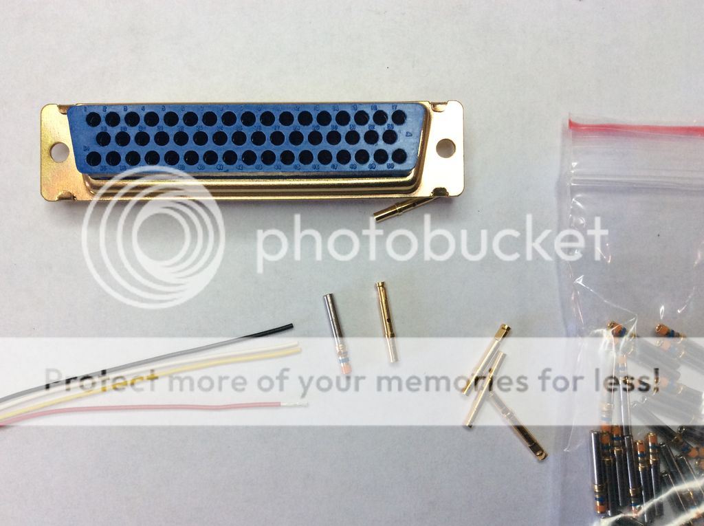
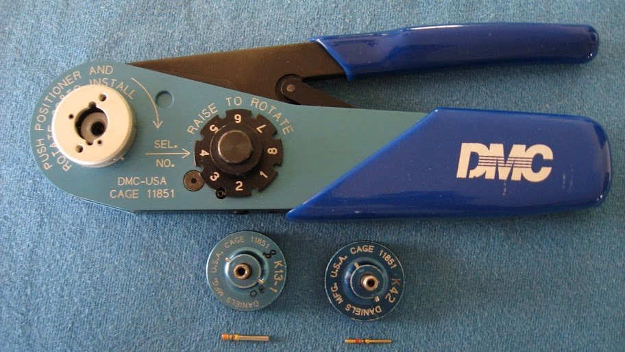
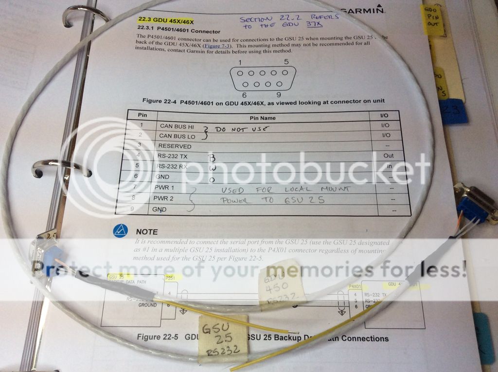
 the plain brass colored ones came with the config module. The colored stripe ones came with the backshell kit that came with the 450. If I were to try and flip the pins end for end, the crimp wire size would be too big and the socket would be too small to fit the back of the 450 display. And, the pins would not lock into the connector like they should.