What's new
Van's Air Force

Don't miss anything! Register now for full access to the definitive RV support community.

RV-12 Dihedral and the angle of attach

joedallas

Well Known Member
After talking with team X at Garmin I decided to put the GMU 22 Magnetometer in the wing to avoid interference from the other electronics in the aircraft, with the battery in the tailcone I need a alternate location for the Magnetometer.

To mount the GMU 22 Magnetometer in the wing I need to know the Dihedral and the angle of attach of the RV 12 Wing.
If anyone can help it will be appreciated.

Thanks
Joe Dallas
 
Is it possible they asked for the angle of incidence? Angle of attack is not a constant.
 
I need to get the magnetometer as level as I can in straight level flight at cruise.
a line thru the cord in level flight compared to the relative wind.

I think this is between about 2? to 4? ? :eek:

I am not sure I think that is the angle of attach compared to the relative wind.
Thanks
Joe Dallas


Is it possible they asked for the angle of incidence? Angle of attack is not a constant.
 
You probably already know this but ...

... the SLAS/ELSA versions of the RV-12 with a G3x touch place the GMU 22 in the location of the Dynon AHRS. You can get the GMU 22 mount to use the existing AHRS bracket from Vans.

Where have you located your battery?
 
Joe, as Larry said, you want the angle of incidence which is relative to a line through the fuselage, not the relative wind. Don't know what the number is for the -12, although 4 deg is probably in the ballpark.
 
Battery Location

The battery is in the tailcone to close to the location that vans used for the GMU 22 mount.


Thanks

Joe D


QUOTE=Rick_A;987784]... the SLAS/ELSA versions of the RV-12 with a G3x touch place the GMU 22 in the location of the Dynon AHRS. You can get the GMU 22 mount to use the existing AHRS bracket from Vans.

Where have you located your battery?[/QUOTE]
 
Confused

Is the longeron level in level flight.

If it is then what is the angle of the cord line of the wing to the longeron with no flaps.

This is confusing, maybe a good night sleep and the brain may kick in, or not.

Thanks
Joe D


Joe, as Larry said, you want the angle of incidence which is relative to a line through the fuselage, not the relative wind. Don't know what the number is for the -12, although 4 deg is probably in the ballpark.
 
Joe, this is a don't overthink it type of deal. It is good for the magnetometer to be around level on average. Airplane designers would be expected to want the fuselage to be around level in cruise, for drag reasons if nothing else. The angle between the fuselage and the wing is the incidence, so that is what you want to know. Seconds of arc don't matter much here. The fuselage angle to level will vary with speed and loading. Small heading errors due to the magnetometer not being quite level will be of small consequence.
 
Last edited:
I would just set it parallel to the cockpit rail and not worry about what the wing angle of incidence is. That should be level enough.
 
This is too close to my canopy lock.
A_04_02_06.jpg


From the Garmin Installation manual ( Revision S ) March, 2015 190-01115-01
In general, wing mounting of the GMU 22 magnetometer is preferred.
Fuselage mounting is less desirable because of the numerous potential disturbances that interfere with operation.
Disturbance Source
Electric motors and relays, including servo motors............... 10 Feet ( 3.0 meters )
Any electrical device drawing more than 100 mA Current.......3 Feet ( 1.0 meter )

Thanks

Joe D


Would this location work for you? It works fine for my GRT magnetometer.

http://www.vansairforce.com/community/showthread.php?t=113295

Regards,
 
From the Garmin Installation manual ( Revision S ) March, 2015 190-01115-01
In general, wing mounting of the GMU 22 magnetometer is preferred.
Fuselage mounting is less desirable because of the numerous potential disturbances that interfere with operation.
Disturbance Source
Electric motors and relays, including servo motors............... 10 Feet ( 3.0 meters )
Any electrical device drawing more than 100 mA Current.......3 Feet ( 1.0 meter )

The auto pilot servo and my battery are to close

Joe D


Sounds like a lot of extra work, Joe. What's wrong with the Vans design?
 
Last edited:
Over thinking

The story of my life, over thinking and reading all the technical information I can find.

I looking for the average line that the cord of the wing goes thru the air in level flight at cruse speed.

The magnetometer is in the wing, the angle of incidence is in reference to the fuselage not level flight line ? ( the line the airfoil goes thru the relative wind to support level flight at gross weight and cruse speed ) This angle should be known based on a wing performance chart.

This should be the starting point to set the magnetometer ( this should give me the best heading results in cross country flights )

I do not have a aeronautical engineering background. I know just enough to be confused.

If I could get it within 30 minutes (.5°) I will be ok.

I will call vans to see if they can help.

Thanks All

Joe Dallas


Joe, this is a don't overthink it type of deal. It is good for the magnetometer to be around level on average. Airplane designers would be expected to want the fuselage to be around level in cruise, for drag reasons if nothing else. The angle between the fuselage and the wing is the incidence, so that is what you want to know. Seconds of arc don't matter much here. The fuselage angle to level will vary with speed and loading. Small heading errors due to the magnetometer not being quite level will be of small consequence.
 
Last edited:
This is probably the best answer

This is probably the best answer and close enough

I will check to see if the spar is 90° to the rail.

Thanks

Joe D


I would just set it parallel to the cockpit rail and not worry about what the wing angle of incidence is. That should be level enough.
 
Last edited:
Joe, if you really want a project consider shielding the servos and battery leads with Mu metal (i.e. High permeability). Then you can put the magnetometer in the fuselage.

Rich
 
Rich
I had a talk with Garmin tech support yesterday, they really prefer the magnetometer in the wing.
Garmin sad that the magnetometer should be within a 2 or 3° from level.
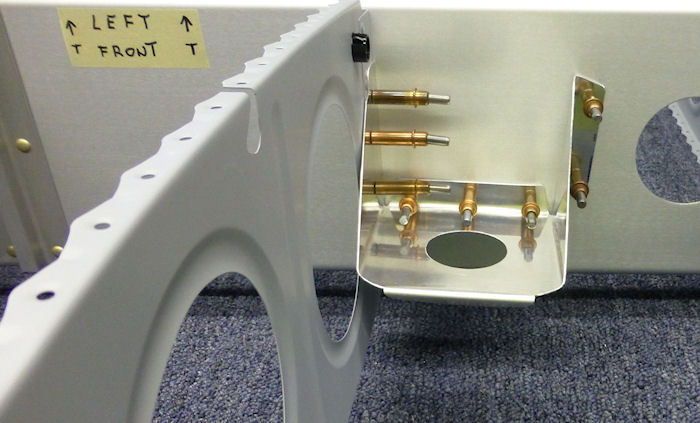
I installed a tray in the wing 90° to the Spar and 5° down to adjust for the wing dihedral.
The hole for the magnetometer is not to size, I will open it when I get the install kit I ordered from Stein Air.
42_03_02A.jpg


Vans RV12 has removable wings so I think that is why they installed it in the second best location the tail.
Removing the wings and taking the aircraft to the airport on a trailer every time I want to go flying don't work for me. ( the wings will only come off to get it to the airport )
I have my fuel tanks in the wings and will be installing a six cylinder engine that weights more than the Rotax, causing me to put the battery in the tail.
The high amp load from the charging system makes it to difficult to shield the magnetic inference and the pitch servo adds to the problem.

Thanks

Joe D


Joe, if you really want a project consider shielding the servos and battery leads with Mu metal (i.e. High permeability). Then you can put the magnetometer in the fuselage.

Rich
 
Last edited:
This is too close to my canopy lock.
A_04_02_06.jpg


From the Garmin Installation manual ( Revision S ) March, 2015 190-01115-01
In general, wing mounting of the GMU 22 magnetometer is preferred.
Fuselage mounting is less desirable because of the numerous potential disturbances that interfere with operation.
Disturbance Source
Electric motors and relays, including servo motors............... 10 Feet ( 3.0 meters )
Any electrical device drawing more than 100 mA Current.......3 Feet ( 1.0 meter )

Thanks

Joe D
Is that a big hole cut into the back of your roll bar? :eek:
 
Scott
Vans has a very well designed aircraft
I have never badmouthed anything that Vans designed.
With all due respect the EEK Smilies Is uncalled for.

The question is ok but the predetermined criticism is not appreciated.

Do you have any calculations on the total bending moment of my design
The hole in the NA of the roll bar and the material that I added Increases the top and bottom of the cord more than make up for the shift of the NA.
Also I have never recommended that anyone copy my design.
I think that EAA means Experimental Aircraft Association
I have a engineering background and have been designing things all my life
I can assure you that completed design is as strong or stronger than the original, and I will bet my life or any amount of money you would like to wager.

Scott even with the disclaimer at the bottom of your Post ( Any opinions expressed in this message are my own and not those of my employer ) your opinion carries more weight than the average post, that comes with some reasonability.

With all that said I again think vans has designed all the aircraft to a very high standard.

Please no disrespect intended.

Thanks
Joe Dallas


Is that a big hole cut into the back of your roll bar? :eek:
 
Last edited:
Scott
Vans has a very well designed aircraft
I have never badmouthed anything that Vans designed.
With all due respect the EEK Smilies Is uncalled for.

The question is ok but the predetermined criticism is not appreciated.

Do you have any calculations on the total bending moment of my design
The hole in the NA of the roll bar and the material that I added Increases the top and bottom of the cord more than make up for the shift of the NA.
Also I have never recommended that anyone copy my design.
I think that EAA means Experimental Aircraft Association
I have a engineering background and have been designing things all my life
I can assure you that completed design is as strong or stronger than the original, and I will bet my life or any amount of money you would like to wager.

Scott even with the disclaimer at the bottom of your Post ( Any opinions expressed in this message are my own and not those of my employer ) your opinion carries more weight than the average post, that comes with some reasonability.

With all that said I again think vans has designed all the aircraft to a very high standard.

Please no disrespect intended.

Thanks
Joe Dallas

Well......I am glad we got that out of the way.......:confused::eek::confused::eek:
 
Please no disrespect intended.

And none intended by me either, so I will adjust the context of my post....

Builders see things posted on VAF that they assume if someone else did it, then it is probably ok for them to do also.
This can be a very dangerous situation, because as you have pointed out, they would not have all of the information.

Having said that, I still have some serious concerns about the hole in your roll bar (even without seeing any calculations you have done). One thing that concerns me is you mention neutral axis, but the rectangular hole you made is no where near to being centered on the neutral axis. In fact it is cut directly adjacent to what we could call the lower cap of the roll bar. I know you know that, so I am just mentioning that for others that might consider doing the same; in hopes they will use caution if they consider copying it.

Best wishes with your project.
 
Thanks Scott, there is so many ways to look at what will happen in a crash.
Your concern is a good thing and nobody should follow any design that they do not totally understand.
The difference between uniform load and point load make a big difference.
I be leave that I took into consideration the possible loads that can be applied in a crash.
Remember a truss has all its support from the top cord and bottom cord and the bracing keeps them parallel the roof deck acts as a diaphragm and keeps the truss straight and from rolling
The original design is very strong and the modified design should equal or exceed that design
This is not a endorsement of my design.
As on my web site.
(Disclaimer : Information contained on this Site may be out of date and /or inaccurate - Please Confirm any important data with a reliable source.)

My aircraft will be listed as a RV12M to keep it from bringing any bad publicity to vans Aircraft

Also.
CA2_e58262b34996b5fe2af686d53d25a014.jpg


Scott Thanks Again

Joe Dallas


And none intended by me either, so I will adjust the context of my post....

Builders see things posted on VAF that they assume if someone else did it, then it is probably ok for them to do also.
This can be a very dangerous situation, because as you have pointed out, they would not have all of the information.

Having said that, I still have some serious concerns about the hole in your roll bar (even without seeing any calculations you have done). One thing that concerns me is you mention neutral axis, but the rectangular hole you made is no where near to being centered on the neutral axis. In fact it is cut directly adjacent to what we could call the lower cap of the roll bar. I know you know that, so I am just mentioning that for others that might consider doing the same; in hopes they will use caution if they consider copying it.

Best wishes with your project.
 
Last edited:
That's the "E" in E-LSA I guess

After about a year and half flying my -12 I'm still genuinely in awe of foresight that went into the original Van's design. The creativity on this site for enhancements, changes etc... is "seductive" to many of us, but its also appreciated to have Scott and others to occasionally remind us amateur designers that every single change to the core design (i.e. even deviating on a rivit spec.) has potential downsides. We're also really fortunate however, to still have a regulatory environment that allows the bravest among us to continually innovate.

... will continue to dream about the RV-12A (amphibious), but I will not likely be the first guy to test out the hypothesis...build on!
 
Joe,

You suffer from the same affliction all us engineers have: We just can't resist redesigning stuff! Building ELSA required all my self restraint since I couldn't change anything!😀

Rich
 
Technology marches on exponentially

I wonder how come Bill Gates just didn't come out with windows Ten in 1982 , then he could just coast until now.

Joe,

You suffer from the same affliction all us engineers have: We just can't resist redesigning stuff! Building ELSA required all my self restraint since I couldn't change anything!��

Rich
 
Last edited:
Angle of Incidence (Dihedral)

Short answer: 5?

This is an old thread, but just in case anyone is searching... I'd post photos of it, but can't figure out how to post them. In any event, the dihedral angel between the spar box and wing spar is 5?, which is important for mounting a remote magnetometer, as Joe pointed out earlier.
 
Back
Top