What's new
Van's Air Force

Don't miss anything! Register now for full access to the definitive RV support community.

Red Cube Installation a la Tom Swearengen

Pat Hatch

Well Known Member
Advertiser
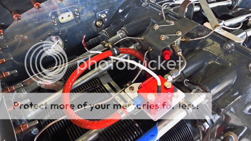
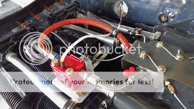
Tom at TS Flightlines made us up a neat little adapter for connecting the Red Cube at the flow divider as seen in the photos below. We've been hearing good things about mounting the Red Cube here so we thought we'd give it a try. Looks like a good solution. Reports indicate less vaporization for hot starts with this location, smoother running engine after a hot start. We'll see.

We mounted the Red Cube on a small piece of .090 between two Adel clamps, one was already there for the s.s. fuel line. Worked out well, good support for the Red Cube and the adapter to the flow divider. Tom made up all of our hoses and did a great job as usual! We had to get a longer than normal #4 hose between the servo and FT-60 as you can see below.


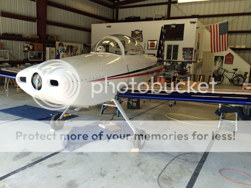
This is Bob Lund's airplane, and as can be seen from the photo below, it's almost ready for first engine start. About all that's left is to hang the 3-bladed MT and finish up some firewall forward details. We used our clear acrylic disk bolted to the crank with spacers to mount the cowl which allows for the correct spacing behind the spinner bulkhead.

Bob wanted to paint the airplane before first flight, which is a first for me, but it has worked out okay so far. Bob built a temporary paint booth in the hangar. First flight will happen by the end of the month.

 
Flex hose?

Are you sure you wouldn't feel better about a flex hose between the cube and the divider? That cube will actually bounce around and vibrate a little since it is attached attached to the cylinder.
Tom is certainly the expert here in this, and I would certainly defer to him.

Vic
 
I know the cylinder should move with the rest of the engine, but having a rigid hose in this environment scares me too, especially since the cube is attached by Adel clamps, which will allow a small amount of motion.
 
Flex hose

My red cube is mounted above the servo on a aluminum flat bar on the crankcase. To compensate for the vibration, I have flex hose on both sides of the red cube as a safety precaution.
 
FWIW, my red cubes in that location seem to last about 400 hours or so on average. Mounted roughly the same as your except no rigid lines.
 
Yep a flex hose would be better, BUT, short hoses of 2-2.5 inches flare to flare are not cost effective, and there is very little space between the 2 stems.
STILL working on a better solution, but Pats adapter is stainless, and I think everything will move together. I'll eventually come up with the combination.
Tom
 
Yes, I agree. Flex hose would be better. I think over time the stainless piece would work harden and possibly crack. So Tom is going to make us up a short piece of hose to go here. Great service from Tom, by the way. I can't say enough good things about his customer care and response. The best.
 
That seems kind of short lived. Is any one else having red cube failures at that rate? What do think is the reason?

Thanks
Brian

FWIW, my red cubes in that location seem to last about 400 hours or so on average. Mounted roughly the same as your except no rigid lines.
 
Brian----I'll check with Kahuna---I want aware that he, or anyone else was having failure issues with the cube. The old Flo Scan yes, but not the cube.

If anyone else out there has had recurring flow transducer failures, please post it here, and let us know!
Tom
 
I believe the red cube will have a shorter lifespan when mounted under the cowling/engine bay due to heat. And I believe the installation instructions I received with mine mentioned something to that effect.
 
Very early failure

My first red cube failed at less than 50 hours and it was mounted to the firewall. Unfortunately EI said the warrantee was 1 year from purchase. Guess that should have been the last piece bought to install. It was 14 months old at the time. Having not heard reports of early failures I don't expect to have more trouble but it is a data point.
 
There is a video somewhere out there on the web that shows how much the cylinders move in relation to the case on these engines and it is significantly more than one might expect. Sure wish I could find it...
 
I am about to move mine from the firewall to the engine mount to eliminate two 90* fittings and level out the hoses coming from the fuel pump and going to the servo. I believe this may help out on my hot starts and pressure fluctuations. The downfall to my plan is it moves the cube closer to the #4 exhaust pipe. I am planning to insulate the cube with leftover fiberfax and the sticky aluminum "Heat Reflective Material" http://www.vansaircraft.com/cgi-bin...104-249&browse=engines&product=cowl_protector I used to protect areas in my cowl that are close to exhaust pipes.
 
One of the issues we have for making packages for the flow transducers is the locations. Being experimental, everyone has a place they want to put their transducer. Well, seemingly thats a simple deal. Just make connecting hoses and all is well. Its not necessarily that simple ( wish it were!)
For most installs, it takes 2 hoses, and those lengths literally are very custom. I've made hoses for alot of you, and I cant recall where 2 installs were exactly alike, with the same hose dimension. (Yep, even an 1/8th of an inch changes things, sometimes dramatically.
So, my intent was to come up with 3 universal locations for injected installs, and design a package that fits. That gives the builder several choices, instead of 1. We started with some recommendations, then did some testing. Several member of Team AeroDynamix flew these installs last year with excellent results. Several of you have flown other locations, with equally excellent results. A few of you tested a custom install and even though the flight hours are low, it seems to be just fine. (Lack of having an engine here to do mock ups is a 'minor' problem.)

So if there is a 'perfect' install some where that works for all the IO320/360/540 applications in RV4, 6, 7, 8, 9, 10, 14 (oh and other makes that we wont talk about here), I'll GLADLY listen and design something.

Tom
 
Has anyone put their Red cube after the boost pump but before the mechanical pump? Instructions say to put after the mechanical pump and before the carb, but just not a good spot on my RV-4 with O-360. Thinking of putting the Red cube in the same spot after the boost pump that my Flowscan was installed in.
 
Has anyone put their Red cube after the boost pump but before the mechanical pump? Instructions say to put after the mechanical pump and before the carb, but just not a good spot on my RV-4 with O-360. Thinking of putting the Red cube in the same spot after the boost pump that my Flowscan was installed in.

I mounted mine after the boost pump, which is in the "battery tunnel." So far it works well and has been accurate.
 
I also installed mine between the boost pump and engine pump on the fuselage floor. I only have 60 hours so far so reliability is unknown. The accuracy seems good though, I?ve made 2 adjustments to the K factor early on and I continue to check it and so far it?s been good. Hot starts seem OK?but I don?t really have anything to compare them to except cold starts which are very good. It has been hot here in Atlanta 90+
 
I put my FT-60 after the throttle body and before the flow divider. I use flexible hoses and so far it has worked well for almost 100 hours. I added an adel clamp to the bottom corner of the throttle body just to ensure the transducer couldn't flex too much and interfere with the throttle linkage.

Build Log

IMG_6232.JPG


IMG_6233.JPG
 
Has anyone put their Red cube after the boost pump but before the mechanical pump? Instructions say to put after the mechanical pump and before the carb, but just not a good spot on my RV-4 with O-360. Thinking of putting the Red cube in the same spot after the boost pump that my Flowscan was installed in.
I venture to say that there are more of them installed in the "tunnel" between the boost pump and the mechanical pump than otherwise. Mine has been installed in the tunnel and the accuracy is within .3 of Gallon, repeatedly and verified. I can't say exactly how many hours on it (don't have my log book here) but it has been in the neighborhood of 350-400 hours and all without any issues thus far.

One other possible downside that I see with this installation is the possible disruption in the airflow inside of the cowl. I don't know for a fact, if this will have any affect but I have tried to keep things as clean and undisruptive to the airflow as possible.
 
Last edited:
Just for giggles, I emailed EI support for a comment on a 'recommendation' for location. Nothing yet, but if I get a response, I'll definately post it, and work on a solution. (I still think between the servo and flow divider is best, and near the flow divider is as good a place as any)
Tom
 
Just for giggles, I emailed EI support for a comment on a 'recommendation' for location. Nothing yet, but if I get a response, I'll definately post it, and work on a solution. (I still think between the servo and flow divider is best, and near the flow divider is as good a place as any) Tom

That train left a while ago. The recommended location is between the servo and the flow divider. The reason is better accuracy when the electric pump is operating.
 
That train left a while ago. The recommended location is between the servo and the flow divider. The reason is better accuracy when the electric pump is operating.

OK I?m going to bite ? So more heat, more vibration, more connections on hot side for how much improvement in accuracy? IMHO :)
 
What technology does the red cube use to sense flow? Positive displacement, Hall effect rotor, vortex sensor, etc.?

General rules for industrial flow meter installation are:

1. Install in a vertical line with upward flow *OR*
2. If installation in a horizontal line is necessary, the flowmeter should be installed such that it is in a low point in the line to ensure the flow element is always flooded.
3. Depending on the technology, there are minimum lengths of inlet and outlet pipe (typically expressed in units of pipe diameters) between changes in pipe direction / fittings / flow disturbances and the flow element. Typical values might be 10 pipe diameters downstream of and 5 pipe diameters upstream of any such disturbances for the element location.

Any information on whether these typical industrial rules are applicable?
 
Has anyone put their Red cube after the boost pump but before the mechanical pump? Instructions say to put after the mechanical pump and before the carb.
Mine is between the gascolator (on the firewall) and the mechanical pump. The reading jumps when the electric pump is turned on, but the electric pump doesn't spend enough time in the "on" state for the totalizer on my MGL gauge to be inaccurate. At least, at every fill-up, I put in exactly what the totalizer says i've used.
 
LOL---yep----and how many DIFFERENT locations between the servo and the flow divider have you plumbed? Vertical sump? Horizontal sump? AFP servo? Bendix? Precision? They all will take different length and style hoses, which, is the object of this exercise. Even moving the transducer 1/2 inch either way CHANGES the lengths of the hoses. Just ask anyone the measured, and were off just a little bit and requested that we 'modify' their hoses.
Just trying to come up with a couple of 'universal' locations, so we can provide a package, AND reduce costs for our clients.
Tom
 
Dave at EI says mount it AFTER all boost pumps and fuel pumps, and lower, or no more than 4 inches higher than the carb, or servo inlet.
Tom
 
Red Cube Installation Update

Tom sent us a short hose to try out instead of the adapter. I like it. This is a much better solution. Here are some photos:


I am all for following good practice, but mine is between the boost pump and mechanical pump, mounted horizontally. I think a lot of people have them there. I tracked fuel for a while and tweaked the conversion factor. On the way to Oshkosh this year I filled both tanks to the bottom of the fillers, flew 4+ hours and used 32.2 gallons per Dynon and 32.0 per the pump when I filled it up to the same place. .2/32 = .625% difference. Plenty accurate for my purposes.

Yes, I was high and LOP to get the average fuel burn down to that rate. I was trying to get to an airport near Chicago to meet my son but Saturday's storms over Missouri made me detour and come up a little short.
 
See---there are lot of installs that at not necessarily to the installation instructions, but work just fine. Even upstream of the last fuel pump, but if if works----
Tom
 
See---there are lot of installs that at not necessarily to the installation instructions, but work just fine. Even upstream of the last fuel pump, but if if works----
Tom

Which leads me back to my original post. If the cube can be mounted anywhere than under the cowl, chances are, it'll perform longer.
 
Brian----warm and fuzzy is good. Keeping it simple AND warm and fuzzy AND cost effective is priceless.
Tom
 
Stainless Steel Fuel Lines

Just a quick observation, but Lycoming SB 342G Diagram 4, recommends
approximately 8 inchs between stainless steel fuel line supports.
This arrangement has moved the supports for cylinder 1 and 3 closer to the spider leaving a fair distance of unsupported fuel line to the injectors.
Also noted that cylinder 2 and 4 fuel lines are missing their supports at the crankcase join (should be 2 supports for each line on that side of the engine).
Cheers
VH-M(y)RV
 
Wow, not only is this a great observation, but it comes all the way from Australia! Thank you.
 
Here's my mounting location, also thanks to Tom...

fxa4pf.jpg


Firesleeve for cube on order...

==dave==
N102FM
 
Here's my mounting location, also thanks to Tom...

fxa4pf.jpg


Firesleeve for cube on order...

==dave==
N102FM

You should consider fabricating a mounting bracket of some kind to tie that to the engine in a more secure manner.
 
Can't see it in the previous picture, but the fuel line is clamped to the eng mount within 6 inches of the inlet to the red cube (per installation instructions).

2jg72vs.jpg


==dave==
N102FM
 
Tom sent us a short hose to try out instead of the adapter. I like it. This is a much better solution. Here are some photos:


I found this thread after realizing that I was going to have to undo a lot of adel clamps holding alternator wires, SCAT tube, and my fuel line, because I buried my single piece fuel line against the sump, and forgot that I had a Red Cube to add to it. This solution is attractive because I might be able to keep my long fuel hose and just add a short length to connect the Red Cube to the spider.
I noticed that YOUR fuel line enters the top of the engine from between the cylinders??? Is your engine missing a baffle below and between the cylinders? My AeroSport IO-360 came with a plate/baffle in that area, effectively blocking air ( and fuel lines) from traveling between the cylinders. I'm plotting where to drill a hole in the aft wall of the #3 baffle to route my fuel line. Not sure how I'll seal it up; rubber grommet, or amble the double snap bushing technique that Van's uses for control cables penetrating the firewall.
Is there any more feedback based on experience with this setup since August?
 
The intercylinder baffles often have a removable panel to allow stuff to pass through. A rubber gromet and some RTV work fine to seal up a fuel line or hose.
 
AA Flyer, yes, Toobuilder is correct, we have a hole with a grommet in the inter-cylinder baffle for passing the fuel line from the fuel servo up between the #1 and #3 cylinders. Works well.
 
Last edited:
Back
Top