What's new
Van's Air Force

Don't miss anything! Register now for full access to the definitive RV support community.

SD-8 Alternator spinning

Good day,

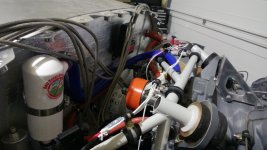
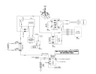
Working on my electrical system I plan on a Z-13/8 architecture with a SD-8 standby alternator. I have read the the outer cage (orange part) is spinning.

Is it only when the alternator is switched ON or all the time ?

Will it be all the time if a self-excitation diode is added (Z-25) ?

Isn't it a problem ? (it feel strange to have something rotating "freely" under the cowl), other than the engine :)

Thanks in advance

Ps : Picture for illustration from a RV-10
 

Attachments

  • SD8 my RV10 factory.jpg
    SD8 my RV10 factory.jpg
    219.7 KB · Views: 133
It is mechanically connected to the engine gear train, so it turns anytime the crankshaft is moved….and yes, that seems strange!
 
Outrunner generator

This class of generator is known as outrunners. The windings are in the center and the outer case with permanent magnets spins.

They have been round a long time but got a lot of traction for use in drones (they work as generators and motors). They are typically wired to produce 3 phase AC output and then rectified and regulated with an electronic controller.

No excitation is needed.

There are some technical and manufacturing advantages for this configuration compared to the more common PMG where the windings are in the case and the magnets spin on the drive shaft.

The big concern with outrunner generators in an aircraft environment is a spinning mass, with a lot of energy, in a failure or accident situation, if it comes loose. Could go from entertaining to life threatening in a heartbeat. There is a need to provide clearance around the case for wiring and plumbing to ensure no contact with the rotating parts.
The Monkworkz offering is in this configuration.

Keith Turner
 
This class of generator is known as outrunners. The windings are in the center and the outer case with permanent magnets spins.

They have been round a long time but got a lot of traction for use in drones (they work as generators and motors). They are typically wired to produce 3 phase AC output and then rectified and regulated with an electronic controller.

No excitation is needed.


Keith Turner

While technically correct, with the SD-8, the rectification is provided for inside the voltage regulator and the VR is powered from the ship bus not the SD-8. Therefore without an external power souce, like a battery, the VR cannot convert the AC to DC to supply power to the bus. Bob has a schematic where a second rectifier and some voltage control is added to the generator feed lines and it's output is spliced into the VR Power input and will produce DC for the VR, allowing it to essentially self-start without a power source. I assume the monk product has this built in to its controller, offering a self-start feature.
 
Last edited:
"While technically correct, with the SD-8, the rectification is provided for inside the voltage regulator and the VR is powered from the ship bus not the SD-8."

Hmmm I'm not so sure about this statement...

The SD-8 is a dynamo - it makes power any time it is being spun by the engine. Rectification of its 3-phase output requires no power. Regulation requires no power and in fact is a bit of a power waster. Ship's power is not provided to the regulator.

A check of the SD-8 wiring diagram provided by B&C shows ship's power being provided only to the over-voltage control relay for the purpose of activating that relay's coil and for providing power to the alternator fail lamp.

Am I missing something?

I have the 30 amp version of this alternator installed on one of my aircraft. It is simply fantastic. Simple, reliable, no brushes or belts to wear out. Truly an amazing piece of hardware. Yes, one does have to get used to that big orange casing spinning all the time and one must secure wiring etc such that nothing can make contact with that orange whirling dervish. Once that adaptation of thinking is made it's pretty much a no-brainer in terms of being one of the most "solid state" power generation systems available.
 
Thanks a lot for your reply, it helps me to better understand this SD-8 and the pros and cons of it for finalizing my architecture !
 
"While technically correct, with the SD-8, the rectification is provided for inside the voltage regulator and the VR is powered from the ship bus not the SD-8."

Hmmm I'm not so sure about this statement...

The SD-8 is a dynamo - it makes power any time it is being spun by the engine. Rectification of its 3-phase output requires no power. Regulation requires no power and in fact is a bit of a power waster. Ship's power is not provided to the regulator.

A check of the SD-8 wiring diagram provided by B&C shows ship's power being provided only to the over-voltage control relay for the purpose of activating that relay's coil and for providing power to the alternator fail lamp.

Am I missing something?

I have the 30 amp version of this alternator installed on one of my aircraft. It is simply fantastic. Simple, reliable, no brushes or belts to wear out. Truly an amazing piece of hardware. Yes, one does have to get used to that big orange casing spinning all the time and one must secure wiring etc such that nothing can make contact with that orange whirling dervish. Once that adaptation of thinking is made it's pretty much a no-brainer in terms of being one of the most "solid state" power generation systems available.

Yes it makes AC anytime it is spinning. HOWEVER, the AC frequency will vary widely based upon the RPM at which it is spinning and this affects the rectified DC voltage. This why your portable gas generator has a governor to hold the RPM stable. Therefore, voltage regulation is critical to creating safe DC output; Not just rectified DC. The voltage regulator portion of the little VR box is a microprocessor and needs stable DC to work. However, the VR is what provides the regulated DC. Therefore the catch. Knuckles knows this and why he created an optional approach to add an external rectifier and voltage cap, so this could have a way to self-start. I am not a EE, but am smart enough to trust Bob and he wouldn't have created the special approach if it wasn't necessary to achieve this capability. If you search for his drawings, you will see his optional schematic for a self-starting SD-8.

Their VR box has two connection pairs. One goes to the Dynamo and the other goes to ship bus. It is this bus connection that is the power input, as well as the output.
 
Last edited:
Like most things the devil is in the details.

There are a number of control strategies that can be used to regulate a variable frequency, variable voltage output provided by either an inrunner or outrunner PMG.
There are two methods that are most commonly used in the rectification and regulation.

1. SCR’s are used to control the conduction angle of the incoming variable frequency, variable voltage in either a half or full bridge topology. The resultant waveform is then smoothed though a filter, compared with a reference voltage and the conduction angle adjusted as necessary to maintain the correct output voltage.
2. The three phase generator output is rectified, filtered and then fed to a high frequency switched mode regulator that controls the output voltage based on an internally generated reference.

The advantages of the first strategy is that the power is only handled once so the overall efficiency can be higher. The disadvantages are that the filter components need to be bigger and more complex to handle the lower frequency chopped up waveform and even then the output ripple is likely to be higher.

The generator for the Rotax IS 9000 series engines falls in this general category even though the generator is an in runner. The other issue is the complexity of the regulator control laws to handle step load changes and the large range of input voltage and frequency.

The second topology has the advantage of providing excellent regulation, low output ripple, smaller less complex filter components, simpler control laws for regulation, excellent ability to handle step load changes and arguably more benign failure modes. The disadvantage is lower overall efficiency because the power is handled at least twice.

The design strategy and resulting topology chosen is usually considered to be intellectual property and not disclosed, so I can’t help with identifying specific manufacturers with particular topology.

Depending on the particular circuit design chosen both topologies may or may not require an external reference to be supplied from ships power either way is possible.

The low minimum RPM for direct drive engines results in a definite low RPM cut off for this type of generator.

For geared engines, like the Rotax, that idle at 2000 RPM the cutoff is below the practical range of engine RPM.

Keith Turner
 
Just to add on to my last post.
The low RPM power output cutoff for this type of generator means that for a fixed pitch prop aircraft on approach with the power back at idle, there is a high probability that the engine RPM is below the power generation cutoff.

If you have designed your electrical system so that your Inrunner PMG is a critical source of power to your ECU etc. and are already having a bad day dealing with system failures, it could get much worse.

Being on final and having to dust off ones glider flying skills could result in a failing grade.

Keith Turner
 
Thanks again !

My engine will not be electrically dependent (2 mags) so this standby alternator will actually be only used to power essential avionics for an extended period of time if needed through an essential bus.

I have picked up Z-13 for it's simplicity and I believe it's exactly what I need but I am not convince if the SD-8 is good or shoud be replaced by a BC410-H for instance using the same architecture.

I will brainstorm and post some more questions...

Thanks again for your help
 
I chose to go with the BC-410H as a backup alternator.

If the engine is turning, I want the alternator to be providing power.

The trade is the extra weight of the BC-410H compared to the PMG offerings versus the wider shaft speed operating range of the BC-410H particularly at the low-speed end of the range where it will always deliver power - but not the full rating.

The overall efficiency of turning shaft horsepower into electrons is likely to favor the BC-410H although that would need to be verified (but that discussion would need to be moved to the primer wars section)

Since the BC-410H has brushes for the field connections there may be a maintenance penalty for the BC-410H also.

The installation cost is pretty much a wash.

How you trade the benefits is a personal choice.

Keith Turner
 
Amps vs RPM

I chose to go with the BC-410H as a backup alternator.

If the engine is turning, I want the alternator to be providing power.

The trade is the extra weight of the BC-410H compared to the PMG offerings versus the wider shaft speed operating range of the BC-410H particularly at the low-speed end of the range where it will always deliver power - but not the full rating.

The overall efficiency of turning shaft horsepower into electrons is likely to favor the BC-410H although that would need to be verified (but that discussion would need to be moved to the primer wars section)

Since the BC-410H has brushes for the field connections there may be a maintenance penalty for the BC-410H also.

The installation cost is pretty much a wash.

How you trade the benefits is a personal choice.

Keith Turner

Just checking in but my BC-410H will not produce any amps below 1,100 RPM. Starting at 1,100 it will produce 2 to 3 amps and at 1,500 amps will produce approximately 50% output. Normal ?
 
Which regulator do you have paired up with your BC-410.

I will dig out the test results I took during my initial checkout. I recall that the BC-410 regulator voltage is set lower than the main 60 amp belt driven alternator. As the engine RPM is increasing the point where the field current starts reducing indicates that the regulator is moving into the linear control range. I seem to remember that it produced about 5 amps at 12.5 volts at 900 RPM. I have a CS prop so I am usually above 900 on final approach. I’ll dig out the data.

Keith Turner
 
Just checking in but my BC-410H will not produce any amps below 1,100 RPM. Starting at 1,100 it will produce 2 to 3 amps and at 1,500 amps will produce approximately 50% output. Normal ?

Yes, that's pretty much expected. At anything approaching a normal cruise flight profile it will hold all normal loads - you'll have to expect to pull some from the battery during the short approach and landing.
 
LR3D

Which regulator do you have paired up with your BC-410.

I will dig out the test results I took during my initial checkout. I recall that the BC-410 regulator voltage is set lower than the main 60 amp belt driven alternator. As the engine RPM is increasing the point where the field current starts reducing indicates that the regulator is moving into the linear control range. I seem to remember that it produced about 5 amps at 12.5 volts at 900 RPM. I have a CS prop so I am usually above 900 on final approach. I’ll dig out the data.

Keith Turner

LR3D is my regulator set at 14.2 volts.
 
This discussion has piqued my curiosity and, as a result, I've had a conversation with TJ at B&C. As always, TJ's response was as patient as it was informative.

As has previously been stated, the SD-8 does indeed use a switch-mode shunt style regulator and it does indeed require a bootstrap connection to +12VDC to get it started.

The alternator I have, the 30 amp unit, uses a different regulator. TJ is investigating as to whether it would be possible to make it self-exciting. I'll report back if he is able to share any additional details.

This discussion thread has proven to be very educational to me and I thank those who have brought solid data to the discussion.
 
Good day,

Attached the Z-25L diagram from Bob Nuckolls. I believe by adding those diodes to start the flow of the SD-8 with a battery out of service and following for the rest diagram Z-13/8, I will be covered for alternator u/s, battery u/s, main contactor u/s.

Exactely what I need !

Thanks again...
 

Attachments

  • Z25L SD8.jpg
    Z25L SD8.jpg
    112.1 KB · Views: 60
Hmmm that diode arrangement would be quite a bit more challenging with my 30-amp alternator as it features a 3 phase output. Going to have to think about this for a bit...
 
Concerning the need or not of a battery to "start up" the SD-8, I have asked B&C their opinion if the Z-25 (Self-Excitation Feature) modification has to be added to guarantee start with a main alternator and battery u/s and will post when I get an answer.

What is strange is that this self-excitation mod was present in diagram Z13 rev Q (2008) but removed from Z13 revision T (2014)...

Here is a quote from aero electric book : Unlike their fielded cousins, permanent magnet alternators may run well with a battery off line if you add a computer grade electrolytic capacitor across its output for filtering. CAUTION some regulators supplied with PM alternators still require a battery to be present before they will "start up"
 
Back
Top