scsmith
Well Known Member
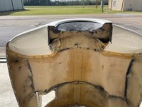
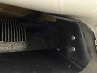
A key area to check on the baffles and cowl are the diffuser ramps that are attached to the inside of the upper cowl.
Is is surprising how often I find an airplane that has those with the ends open, creating a HUGE leak tunnel through to the low-pressure side.
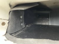
I have seen some installations where there are baffle seals on both the inboard and outboard ends of the difffusers, so being open wouldn't matter in that case, but it is much more common to just have baffle seals on the outboard end and the inboard end is inside the upper plenum. If the ends are open, forming a tube, it is a big leak.
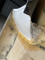
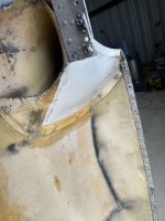
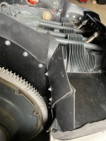
If your diffuser tunnels are open on the ends, tape over them with duck tape and and flight test to see the difference.
Is is surprising how often I find an airplane that has those with the ends open, creating a HUGE leak tunnel through to the low-pressure side.
I have seen some installations where there are baffle seals on both the inboard and outboard ends of the difffusers, so being open wouldn't matter in that case, but it is much more common to just have baffle seals on the outboard end and the inboard end is inside the upper plenum. If the ends are open, forming a tube, it is a big leak.
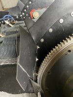
If your diffuser tunnels are open on the ends, tape over them with duck tape and and flight test to see the difference.