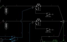
9/13/2023 - Updated drawing at post #149. EFI/EI on single bus with dual feed. EFI/EI bus and avionics busses supplied via MIDI fuses.
I'm going to post recent work, and risk being branded a heretic.
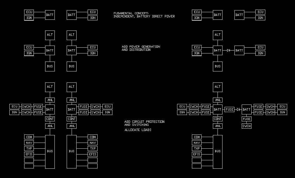
Opinion...the current approach to power supply wiring has become far too complicated, both physically and operationally. Both aspects can be simplified, if we throw out some fixed thinking.
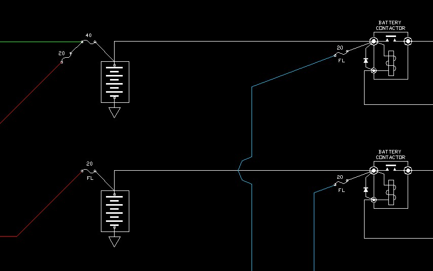
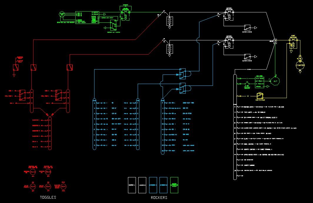
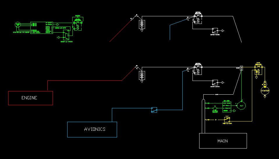
The attached is a dual bus, dual battery, dual generation system, supporting an SDS EFI /EI, and a three screen G3X/G5. Batteries are ETX900's. Primary alternator is a B&C L60 w/ an LR3D. Backup generator is an MZ-30L. The G5 has its own battery.
Yellow: cranking system.
Green: power generation.
Red: EFI/EI.
Blue: avionics.
White: typical main bus functions.
System is effectively modular.
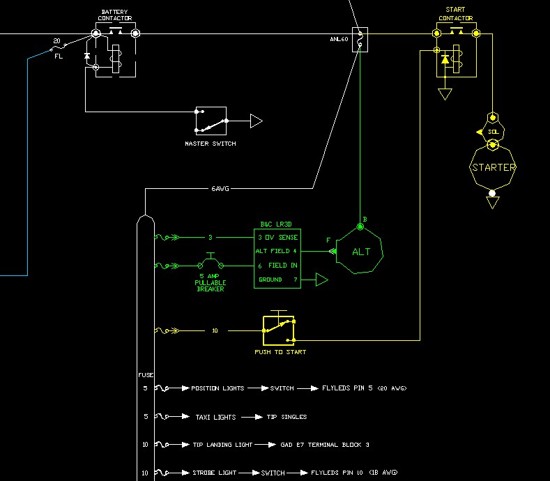
Nothing exotic at the main bus. No field switch, just a pull breaker, which is mostly relegated to being a test function. The LR3C handles overvoltage.
The leftmost avionics busses dovetail with the dual power inputs on many Garmin products. Single input avionics go on a bus with dual feeds. Avionics may be fed from either battery, or one.
The SDS power supply is critical. Again, feed is from either battery, or one. Each coil/fuel pump switch is a three position Honeywell 2TL1-10 wired as OFF/COIL ON/COIL & FUEL PUMP ON.
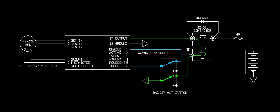
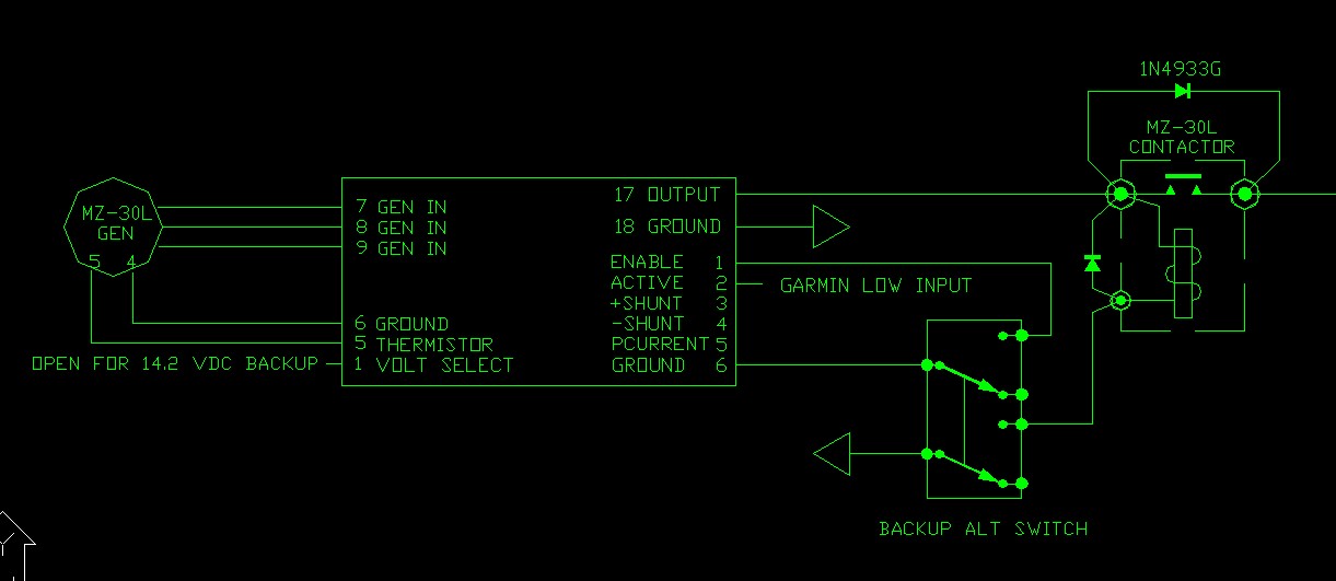
The MZ-30L has several interesting features, foremost being self-start and electronic current limiting. Here the primary purpose is powering the SDS system no matter what. As a secondary mission, it will also support limited avionics and main bus function. It's wired with a relay or contactor because it's connected to battery #1, and the regulator does have a small parasitic draw. With the ENABLE switch closed, it is in standby, and comes online if bus power drops to battery voltage or less.
Note a typical Monkworkz application ties the regulator output to the switched side of the main contactor. In that case, if set as an auto backup (regulator pin 1 open), it would not need a relay. Again, here the goal was to feed an SDS bus with the masters open.
Operational simplicity should be a major design goal. When the spit hits the fan, pilot IQ tends to go out the window, at least for a little while. So, let's make the switching intuitive, and more important, arrange it so it requires little or no pilot action given power failure.
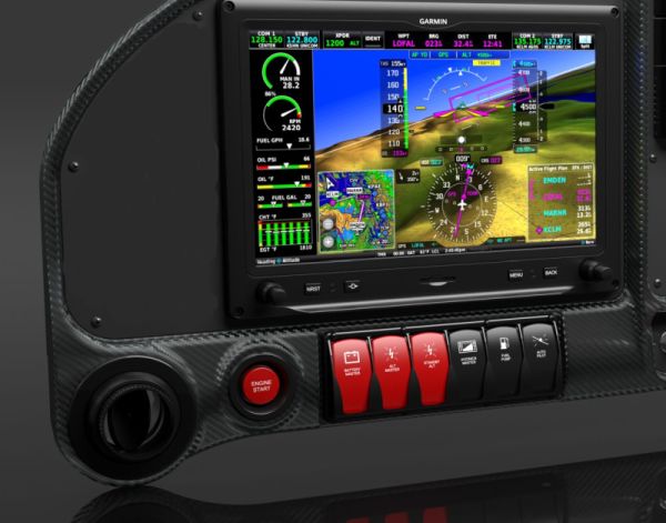
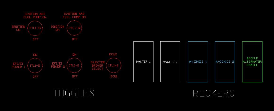
This is going in an Aerosport panel, so all the toggles to the left of the pilot's display are for the SDS EFI/EI. The critical rockers (DPST Carlings) are below the display. Note the conceptual similarities to traditional systems. It's basically mags and masters.
For a critical flight regime (like departure), the switch settings are dead simple...they're all UP, with one exception, INJECTOR DRIVER SELECT. Given power loss at 300 feet over the trees, the entire pilot response is flip that one switch, and change tanks. Again, pretty familiar.
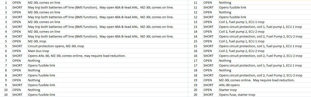
First pass, a basic "open or short" review doesn't turn up any critical issues, but if I missed something, hey, I'm all ears.
On a bad day, both main contactors can be opened, which immediately dumps the large loads and brings the MZ-30L on line. Avionics load is about 10A, maybe 13 running autopilot servos, and can be less. The pilot has access to both batteries and the MZ-30L, in any combination.
On a really, really bad day, the MZ-30L carries the SDS, and the G5 is on internal battery.
I'm going to post recent work, and risk being branded a heretic.
Opinion...the current approach to power supply wiring has become far too complicated, both physically and operationally. Both aspects can be simplified, if we throw out some fixed thinking.
The attached is a dual bus, dual battery, dual generation system, supporting an SDS EFI /EI, and a three screen G3X/G5. Batteries are ETX900's. Primary alternator is a B&C L60 w/ an LR3D. Backup generator is an MZ-30L. The G5 has its own battery.
Yellow: cranking system.
Green: power generation.
Red: EFI/EI.
Blue: avionics.
White: typical main bus functions.
System is effectively modular.
Nothing exotic at the main bus. No field switch, just a pull breaker, which is mostly relegated to being a test function. The LR3C handles overvoltage.
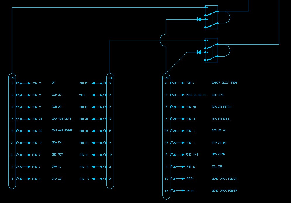
The leftmost avionics busses dovetail with the dual power inputs on many Garmin products. Single input avionics go on a bus with dual feeds. Avionics may be fed from either battery, or one.
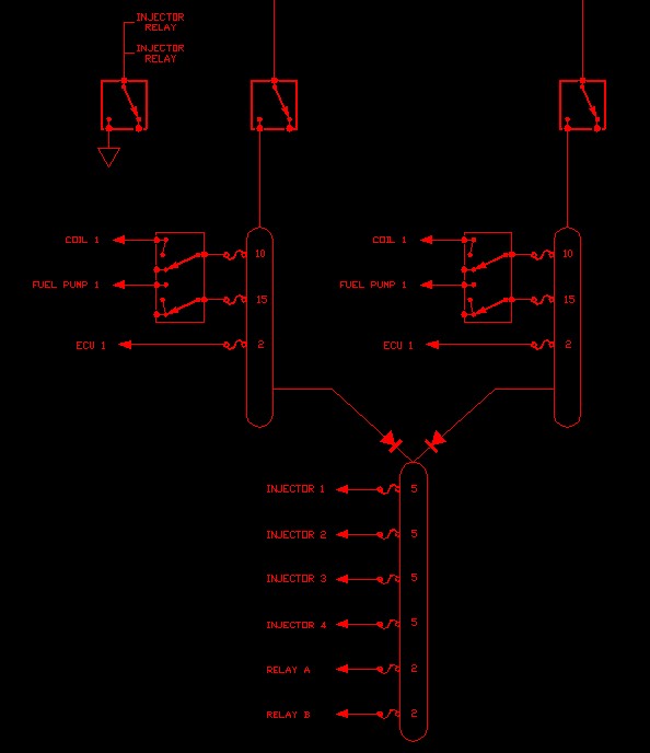
The SDS power supply is critical. Again, feed is from either battery, or one. Each coil/fuel pump switch is a three position Honeywell 2TL1-10 wired as OFF/COIL ON/COIL & FUEL PUMP ON.
The MZ-30L has several interesting features, foremost being self-start and electronic current limiting. Here the primary purpose is powering the SDS system no matter what. As a secondary mission, it will also support limited avionics and main bus function. It's wired with a relay or contactor because it's connected to battery #1, and the regulator does have a small parasitic draw. With the ENABLE switch closed, it is in standby, and comes online if bus power drops to battery voltage or less.
Note a typical Monkworkz application ties the regulator output to the switched side of the main contactor. In that case, if set as an auto backup (regulator pin 1 open), it would not need a relay. Again, here the goal was to feed an SDS bus with the masters open.
Operational simplicity should be a major design goal. When the spit hits the fan, pilot IQ tends to go out the window, at least for a little while. So, let's make the switching intuitive, and more important, arrange it so it requires little or no pilot action given power failure.
This is going in an Aerosport panel, so all the toggles to the left of the pilot's display are for the SDS EFI/EI. The critical rockers (DPST Carlings) are below the display. Note the conceptual similarities to traditional systems. It's basically mags and masters.
For a critical flight regime (like departure), the switch settings are dead simple...they're all UP, with one exception, INJECTOR DRIVER SELECT. Given power loss at 300 feet over the trees, the entire pilot response is flip that one switch, and change tanks. Again, pretty familiar.
First pass, a basic "open or short" review doesn't turn up any critical issues, but if I missed something, hey, I'm all ears.
On a bad day, both main contactors can be opened, which immediately dumps the large loads and brings the MZ-30L on line. Avionics load is about 10A, maybe 13 running autopilot servos, and can be less. The pilot has access to both batteries and the MZ-30L, in any combination.
On a really, really bad day, the MZ-30L carries the SDS, and the G5 is on internal battery.
Last edited:

")