
Van's Air Force
You are using an out of date browser. It may not display this or other websites correctly.
You should upgrade or use an alternative browser.
You should upgrade or use an alternative browser.
What's the theory on F1 Rocket Air Inlet Shape and Placement
- Thread starter Bob Axsom
- Start date

F1Boss
Well Known Member
Yep!
Milt knows me better than I thought he did! TLAR was our process, and it worked pretty good! But, I resent being called an artist!
We wanted a good ram recovery scoop when we got going with the F1 cowl (c1998). The 1st effort was curved top & bottom, and did OK. I wanted a bit more pressure, and accidentally designed an efficient low speed inlet by straightening the upper curve into a straight line across and increasing the edge radius. The low speed inlet gave another inch or so of pressure -- Ole 84 would show 31"MP at Taylor (600' elev) on the takeoff roll, which is without the benefit of fwd speed for ram effect! At Reno, this inlet gave 26" at race speed (195KIAS) and 5000'MSL.
Filter in/filter out: no difference.
Marcus is fitting one to a local RV7 -- might wait to see what he gets in terms of MP increase before you go much further.
The Rod Bower system seems to work pretty good too, but this is a high speed inlet design, and that sort of inlet is very picky about inlet lip radius and the duct behind it; get the duct wrong, and all your work is for naught.
Carry on!
Mark
Last edited:
The low speed inlet gave another inch or so of pressure -- Ole 84 would show 31"MP at Taylor (600' elev) on the takeoff roll, which is without the benefit of fwd speed for ram effect! At Reno, this inlet gave 27" at race speed (195KIAS) and 5000'MSL.
Mark
Mark, how do you account for the extra 1" of MAP under both of these conditions? At Reno at the TAS you give you would get 1.1" rise over the field's approximately 25" or about 26.1" with total pressure recovery. At Reno that would require an inlet velocity of 228 kts. I'm not familiar with any method to get more dynamic pressure than can be gotten from forward speed. Is it possible that your MAP sensor has an error? 'Just asking.
F1Boss
Well Known Member
Wishful seeing?
Hey Paul:
I recall running 26 squared, now that you jogged my memory hard enough. I was thinking I ran at 2700, but I know that plane was fastest at 2600RPM...and the numbers were squared up. Fuel flow at about 22GPH -- again, if memory serves.
Dunno about the T/O MP at Taylor -- that's what I saw normally with that setup. One fella I let go fly the thing asked if it had a turbo! The gage read normal pressure (about 29.5") with the engine off, depending on field baro pressure.
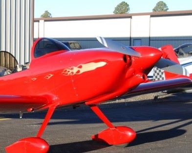
Doug R can confirm or deny all this - he has the plane now. It's the RED one, ya know...
Carry on!
Mark
Hey Paul:
I recall running 26 squared, now that you jogged my memory hard enough. I was thinking I ran at 2700, but I know that plane was fastest at 2600RPM...and the numbers were squared up. Fuel flow at about 22GPH -- again, if memory serves.
Dunno about the T/O MP at Taylor -- that's what I saw normally with that setup. One fella I let go fly the thing asked if it had a turbo! The gage read normal pressure (about 29.5") with the engine off, depending on field baro pressure.
Doug R can confirm or deny all this - he has the plane now. It's the RED one, ya know...
Carry on!
Mark
Last edited:
az_gila
Well Known Member
My guess would be that as opposed to being an aerodynamic consideration it is an artists concept of what is aesthetically pleasing.
...
...and to imitate what a Rocket wants to be....
")
avengingangel
Well Known Member
I never noticed that before..ha
avengingangel
Well Known Member
and here I was thinking it was just to cool the alternator..lol
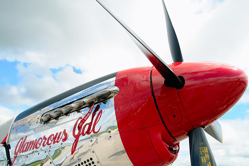
This is no Mustang copy cat
I understand the rationale behind the mustang inlet right up against the fuselage so the air coming off the underside of the spinner is ramped directly into the catcher scoop. The F1 Rocket intake stands off from that intuitive pressure flow as if to avoid something in that zone. The first time I remember seeing anything in print about separating an intake from the adjacent body was in a description of the intake design for the then new F4H Phantom. F1Boss is providing a glimpse into the thoughts behind the F1 Rocket inlet design. Since he did it "he oughta know." Thanks for the feedback.
Oh by the way looking over the photos at www.sportairrace.org under "memories" for Rocket 100 2010 I saw a strange closed point where the induction air inlet should be on Mike Thompson's RV-6. Something is going on there in Taylor. I have to keep my eye on that guy.
Bob Axsom
Special Delivery
Well Known Member
<snip>Oh by the way looking over the photos at www.sportairrace.org under "memories" for Rocket 100 2010 I saw a strange closed point where the induction air inlet should be on Mike Thompson's RV-6. Something is going on there in Taylor. I have to keep my eye on that guy.
Bob Axsom
I agree Bob... pretty suspicious looking!
az_gila
Well Known Member
I understand the rationale behind the mustang inlet right up against the fuselage so the air coming off the underside of the spinner is ramped directly into the catcher scoop. The F1 Rocket intake stands off from that intuitive pressure flow as if to avoid something in that zone. The first time I remember seeing anything in print about separating an intake from the adjacent body was in a description of the intake design for the then new F4H Phantom. .....
The intake stand-off from a boundary layer is a little older than the F4 Phantom....
You just have to look a little further back on the plane that the Rockets want to be....

P51
OK but why are the P51D belly scoop and induction inlet so different. The top Reno racers have all modified the belly scoop but no one has modified the induction inlet. Old article in Sport Aviation went into a lot of detail about the belly scoop, but again not much if any on the induction. Most small turboprops use a scoop that is similar to the P51 belly scoop. Older King Airs, Cheyennes etc mounted the scoop back from the prop a considerable distance. Moving the scoop forward close to the prop results in a substantial increase in performance on these airplanes.
OK but why are the P51D belly scoop and induction inlet so different. The top Reno racers have all modified the belly scoop but no one has modified the induction inlet. Old article in Sport Aviation went into a lot of detail about the belly scoop, but again not much if any on the induction. Most small turboprops use a scoop that is similar to the P51 belly scoop. Older King Airs, Cheyennes etc mounted the scoop back from the prop a considerable distance. Moving the scoop forward close to the prop results in a substantial increase in performance on these airplanes.
Any time you have a sufficient area ahead of a scoop, especially if it's flat, a boundary layer will build up. Moving the inlet away from the surface with a curved dam to shunt the slow boundary layer around the scoop prevents this lower velocity air from entering the inlet which would reduce its efficiency. On a scoop immediately behind the spinner there is no boundary layer to speak of, so it is not necessary to move it away. Since the spinner displaces and speeds up the air flowing around it, there is also the possibility of getting a very slight boost. Except at low speeds, the air velocity increase from a prop, especially in the 200 mph neighborhood, is only about 5-10 ft/sec, not the many mph you feel in ground testing. The velocity increment that the prop adds to the flow actually increases as it flows back in what is described as a vena contracta flow, to the extent that it would be twice as fast at infinity if there were no dispersion! It is this double velocity that is used in calculating the prop's thrust.
That is consistent with my opinion
That is consistent with my opinion which inspired the question. Your post stimulates other thoughts as well. Thanks.
Bob Axsom
Any time you have a sufficient area ahead of a scoop, especially if it's flat, a boundary layer will build up. Moving the inlet away from the surface with a curved dam to shunt the slow boundary layer around the scoop prevents this lower velocity air from entering the inlet which would reduce its efficiency. On a scoop immediately behind the spinner there is no boundary layer to speak of, so it is not necessary to move it away. Since the spinner displaces and speeds up the air flowing around it, there is also the possibility of getting a very slight boost. Except at low speeds, the air velocity increase from a prop, especially in the 200 mph neighborhood, is only about 5-10 ft/sec, not the many mph you feel in ground testing. The velocity increment that the prop adds to the flow actually increases as it flows back in what is described as a vena contracta flow, to the extent that it would be twice as fast at infinity if there were no dispersion! It is this double velocity that is used in calculating the prop's thrust.
That is consistent with my opinion which inspired the question. Your post stimulates other thoughts as well. Thanks.
Bob Axsom
rvmills
Well Known Member
Interesting discussion, for sure!
On Mike's 6, the point is either:
1. A Pressure Recovery module on the lower cowl to speed the flow past the belly...
2. A faired radome for his 2" radar dish...
3. A structure to fair the plugged old induction air inlet when he changed to a snorkel-fed induction via the left inlet...and he doesn't want to build a new lower cowl...yet...
I'm not tellin!
However, I have a similar snorkel-fed induction on the S6, augmented by an unfiltered Ram Air door where that point is on Mike's cowl (though more faired, like a Rocket). I suggested Mike consider that Ram Air mod, but not sure its applicable (Can ya do that on a carbed engine?).
I've been wanting to play with my Ram Air too, and this discussion has me thinking about an F-1 style (or P-51 style) smiley face now...gotta pick Mark's brain on that. However, Tom Martin changed to a Bower Ram Air system on his 270+ mph Rocket, so he must have been listenin' in class that day, eh Mark! Not sure what is best or most effective...and perhaps it'll come after playing with the exit area, when seeing what fairs along the bottom of the belly mo betta.
Lots to learn here, that's for sure!!
Cheers,
Bob
On Mike's 6, the point is either:
1. A Pressure Recovery module on the lower cowl to speed the flow past the belly...
2. A faired radome for his 2" radar dish...
3. A structure to fair the plugged old induction air inlet when he changed to a snorkel-fed induction via the left inlet...and he doesn't want to build a new lower cowl...yet...
I'm not tellin!
However, I have a similar snorkel-fed induction on the S6, augmented by an unfiltered Ram Air door where that point is on Mike's cowl (though more faired, like a Rocket). I suggested Mike consider that Ram Air mod, but not sure its applicable (Can ya do that on a carbed engine?).
I've been wanting to play with my Ram Air too, and this discussion has me thinking about an F-1 style (or P-51 style) smiley face now...gotta pick Mark's brain on that. However, Tom Martin changed to a Bower Ram Air system on his 270+ mph Rocket, so he must have been listenin' in class that day, eh Mark!
Not sure what is best or most effective...and perhaps it'll come after playing with the exit area, when seeing what fairs along the bottom of the belly mo betta.Lots to learn here, that's for sure!!
Cheers,
Bob
Bob_pipedream
Active Member
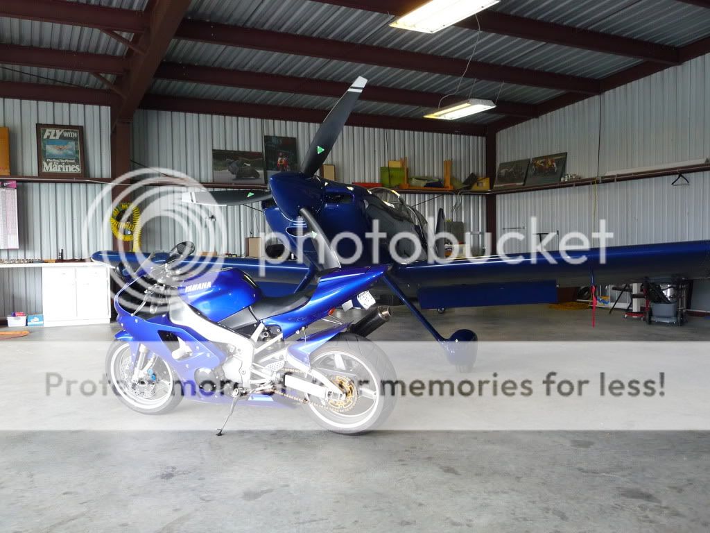
Ram air works well on a carb'd engine. I have a ZX7R jap bike that uses ram air and the incraese in top speed is a lot. I think the earlier non-ram could make 160mph, but the later ram air bikes (P1-P7) could make 174mph (although I have only ever got mine to about 165 as I am bigger than the average Japanese man). Problem is that it does screw up the jetting and the ZX7R with ram effect has a much bigger main jet. I think this is the reason (along with the emissions) that the jap bike manufacturers went to injection quite quickly after they began playing with ram.
rvmills
Well Known Member
Thought I'd reopen this thread, as I've been contemplating some winter cowl mods, and the great discussion of exit work going on in Ken's cowl flap thread, as well as the great info in Dan's Shrinking Exit thread has me looking at many possibilities.
One mod on the to-do list is to redesign my induction air inlet, and this thread has some great discussion I hope to re-energize. Mark Frederick, Greg Nelson and I had some great talks about this at Reno this year, and so far my top choice is to go with one of Mark's curved-bottom, flat-topped low speed inlets, like the one on Ol' 84, as discussed earlier in this thread by Mark.
However, we all had the opportunity to talk with Dave Anders at the Races, and he strongly recommended going with a round inlet, and lowering it to get it away from the thick boundary layer close to the spinner. Reminds me of the Paeser inlet from Speed with Economy...I think.
Seeing Pooner's post earlier in this thread about his success with a round inlet and a conical filter generates a few questions for the brain trust. Would love to hear your collective opinions, and/or get pointed to some references for this area of inlet design.
Here is my current Ram Air inlet. Normal induction air is pulled through a filter in the left cooling air inlet, and fed to the servo via a scat tube. Opening Ram Air bypasses that and provides unfiltered air to the servo. I think I'm losing some MP due to losses in the filter and scat, and gaining some back with Ram (I see about a 0.8" MP rise when I open it in cruise). I'll dump the scat-fed method if I go with a Rocket smily intake or a round intake.
I know I have work to do on my spinner (outer circumference too small for the cowling size, and large lips at the blade openings). My set up seemed to get less ram rise than Greg's, though I was running a faster RPM than he was with his MT prop, which may explain some of the delta...but not all. Those losses I talked about are some of the issue...perhaps.
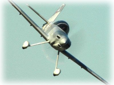
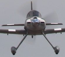
The next few pics are of 4 Rockets with different styled inlets, for comparison and discussion. Would love to hear opinons.
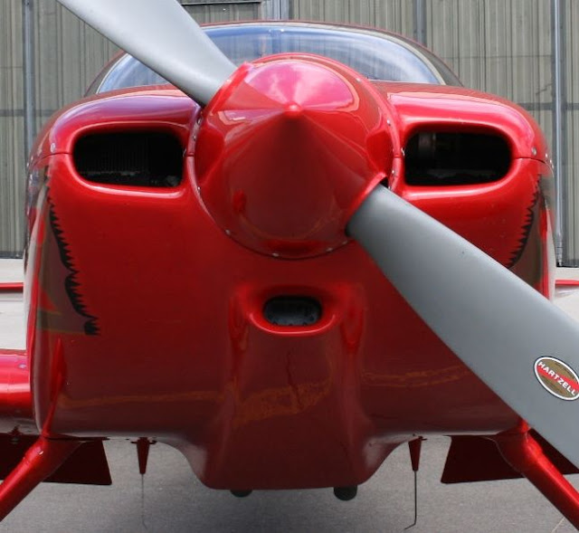
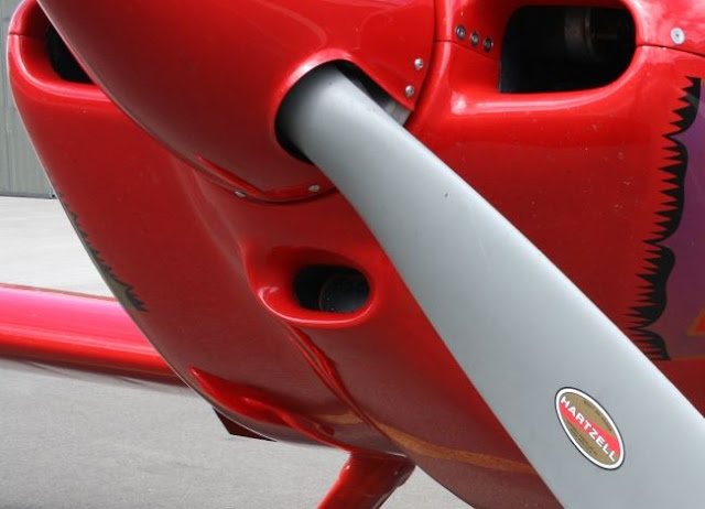
Here is Greg's fast Rocket, with the high speed curved-on-top-and-bottom inlet. He says that, Like Ol' 84, he sees no loss of MP with the filter in place...surprising to me, but he's tested it a lot, and is a meticulous guy...I believe him.
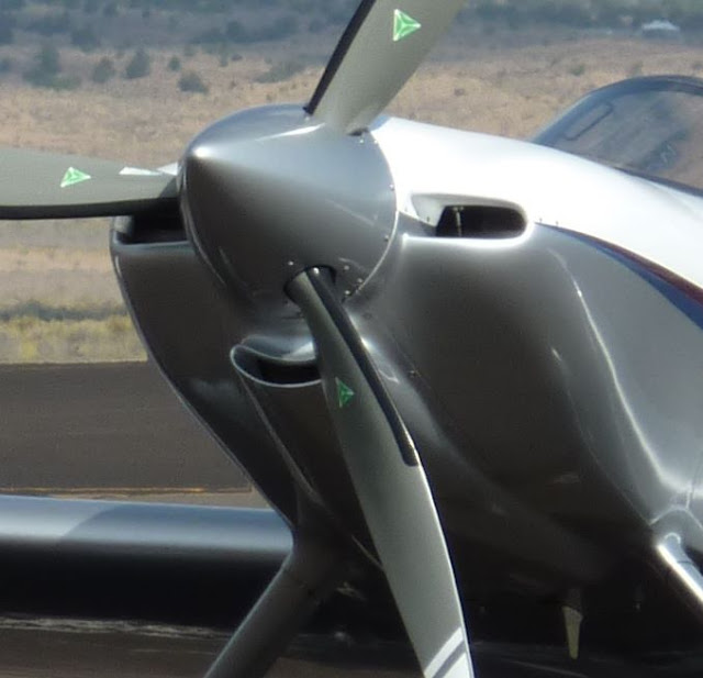
Here is the best pic I can find of Ol' 84's inlet (got any more Mark or Doug?)
Both this and Greg's inlet seem to be moved out and away from the spinner and that boundary layer issue. Neither seem particularly far removed from the spinner though, so I'm wondering how far away is far enough to get good free-stream air.
Here's Mark's current inlet on El Toro. Its for a 550, but its an interesting study of placement near the spinner.
This placement is in top for the TCM motor of course, but looks like Mark took the page out of the P-51 book, and has it right off the spinner. Leads to another question, that being, if you go with a location right at the spinner to get accelerated air coming off the spinner, how close is good, and at what distance when moving away from the spinner do you run into boundary layer issues?
Finally, here's an HRII with what looks like a Bower intake
This is where I'd love to hear Bob's input on his round-inlet set-up, and if you have any pictures, that would be great to see. I'd also be interested in whether you lose MP with the filter in place (if you've tested it with and without).
I think I may use nutplates as Greg did, so I can play with the shape a bit over time. Any thoughts, or vectors to references, are most appreciated!!
Cheers,
Bob
One mod on the to-do list is to redesign my induction air inlet, and this thread has some great discussion I hope to re-energize. Mark Frederick, Greg Nelson and I had some great talks about this at Reno this year, and so far my top choice is to go with one of Mark's curved-bottom, flat-topped low speed inlets, like the one on Ol' 84, as discussed earlier in this thread by Mark.
However, we all had the opportunity to talk with Dave Anders at the Races, and he strongly recommended going with a round inlet, and lowering it to get it away from the thick boundary layer close to the spinner. Reminds me of the Paeser inlet from Speed with Economy...I think.
Seeing Pooner's post earlier in this thread about his success with a round inlet and a conical filter generates a few questions for the brain trust. Would love to hear your collective opinions, and/or get pointed to some references for this area of inlet design.
Here is my current Ram Air inlet. Normal induction air is pulled through a filter in the left cooling air inlet, and fed to the servo via a scat tube. Opening Ram Air bypasses that and provides unfiltered air to the servo. I think I'm losing some MP due to losses in the filter and scat, and gaining some back with Ram (I see about a 0.8" MP rise when I open it in cruise). I'll dump the scat-fed method if I go with a Rocket smily intake or a round intake.
I know I have work to do on my spinner (outer circumference too small for the cowling size, and large lips at the blade openings). My set up seemed to get less ram rise than Greg's, though I was running a faster RPM than he was with his MT prop, which may explain some of the delta...but not all. Those losses I talked about are some of the issue...perhaps.
The next few pics are of 4 Rockets with different styled inlets, for comparison and discussion. Would love to hear opinons.
Here is Greg's fast Rocket, with the high speed curved-on-top-and-bottom inlet. He says that, Like Ol' 84, he sees no loss of MP with the filter in place...surprising to me, but he's tested it a lot, and is a meticulous guy...I believe him.
Here is the best pic I can find of Ol' 84's inlet (got any more Mark or Doug?)
Both this and Greg's inlet seem to be moved out and away from the spinner and that boundary layer issue. Neither seem particularly far removed from the spinner though, so I'm wondering how far away is far enough to get good free-stream air.
Here's Mark's current inlet on El Toro. Its for a 550, but its an interesting study of placement near the spinner.
This placement is in top for the TCM motor of course, but looks like Mark took the page out of the P-51 book, and has it right off the spinner. Leads to another question, that being, if you go with a location right at the spinner to get accelerated air coming off the spinner, how close is good, and at what distance when moving away from the spinner do you run into boundary layer issues?
Finally, here's an HRII with what looks like a Bower intake
This is where I'd love to hear Bob's input on his round-inlet set-up, and if you have any pictures, that would be great to see. I'd also be interested in whether you lose MP with the filter in place (if you've tested it with and without).
I think I may use nutplates as Greg did, so I can play with the shape a bit over time. Any thoughts, or vectors to references, are most appreciated!!
Cheers,
Bob
Last edited:
logansc
Well Known Member
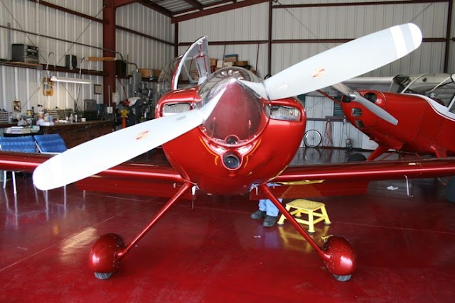
Here's a look at the straight top, curved bottom Rocket inlet:
 [/IMG]
Mine is strictly stock with the F1 'factory' K&N flat filter and a 3" (or so) smooth SCAT/SCEET (whichever one of those has the smooth interior) connecting hose. Just bombed back yesterday from Tappahannock, VA to Ridgeland, SC in a little over 2 hours against a wicked headwind (380 nm direct), so she's getting down the road pretty well. I was running 21"/2,200 rpm at 8,500 and around 12.5-12.9 gph.
Lee...
Toobuilder
Well Known Member
My reading on the subject confirms that a scoop needs to be off the boundary layer - that's a given. However, if this scoop is behind a propeller, it also seems that you want is both as far outboard and as close to the blade TE as you can get. With this in mind, I designed a pitot style inlet for my Hiperbipe to test the theory. Long story short, the actual inlet was a piece of 3"dia tube (with a machined inlet lip) that could slide in and out of the filter housing. The difference in distance between the most forward position (limited by prop TE at full course pitch and a little "shake") and the most aft position was about 4 inches. Flight test confirmed a slight but measurable (0.3in)increase in MP at top speed. I'm doing a ram air scoop on the -8 next, and despite the front induction IO-360, it looks like the scoop is going to end up in roughly the same location as the stock Vans carb induction cowl.
F1Boss
Well Known Member
research
Hey Bob:
I suspect you gonna have to ask the fellas what they are getting in terms of MP with the scoop setup they have installed - then copy the best one! Be careful about claims vs actual numbers - you know how pilots are!
I don't think Tom is getting any better pressure than the Mk.2 F1 inlet, and Pooner is not flying yet, so there is no comparison available there either.
I'm not sure the 550 inlet is optimal - I suspect it could be made a bit larger to slow the inlet air velocity - maybe that will be a winter project along with the exhaust/augmenter installation...
Mr. Axsom has a lot of catching up to do!
Carry on!
Mark
rvmills
Well Known Member
Here's a look at the straight top, curved bottom Rocket inlet:
Mine is strictly stock with the F1 'factory' K&N flat filter and a 3" (or so) smooth SCAT/SCEET (whichever one of those has the smooth interior) connecting hose. Lee...
Thanks Lee..man that is a great looking airplane!!
My reading on the subject confirms that a scoop needs to be off the boundary layer - that's a given. However, if this scoop is behind a propeller, it also seems that you want is both as far outboard and as close to the blade TE as you can get.
<snip> I'm doing a ram air scoop on the -8 next, and despite the front induction IO-360, it looks like the scoop is going to end up in roughly the same location as the stock Vans carb induction cowl.
Sounds like what the Formula racers often do, and what was on one of Paeser's iterations on his plane.
Any picutres Michael?
John's RV-8 with an IO-360 was the fastest in all the SARL competition with Jon Ross close behind.
Bob Axsom
Here's a pic of John Huft's plane from one of the Pagosa Race Memories pages:
Could be the type of thing Dave Anders was talking about at Reno. His thought was to lower it away from the spinner, and get it out towards the free stream more. His point was that Van was definitely on to the right idea with the standard air inlet. How we morph that to an injected Rocket-type cowl is the crux of the matter I'm investigating here.
Hey Bob:
I suspect you gonna have to ask the fellas what they are getting in terms of MP with the scoop setup they have installed - then copy the best one! Be careful about claims vs actual numbers - you know how pilots are!
I don't think Tom is getting any better pressure than the Mk.2 F1 inlet, and Pooner is not flying yet, so there is no comparison available there either.
I'm not sure the 550 inlet is optimal - I suspect it could be made a bit larger to slow the inlet air velocity - maybe that will be a winter project along with the exhaust/augmenter installation...
Mr. Axsom has a lot of catching up to do!
Carry on!
Mark
I do hear ya Mark! I still like the Mk2 Rocket inlet...that is still my top choice...and I know how to get one (I know where you live!
). Plus, we know it works!Lot's of smart guys here, and its fun to bounce this around. Hearing Dave discuss it is always like goin' to school (as you know). I forgot that Tom has the Bower Ram air as well...another fast round inlet...hmmm. But we know its also about the entire treatment...
-inlet shape and size
-lip shape
-placement away from the boundary layer (perhaps, unless you can use the air right off the edge of the spinner...though I do note that both smily ducts and John's round duct are all about the same offset from the cowl surface)
-divergent duct to the filter (I think)
One thing I'm still trying to get my head around is the flow path on the inside of the air inlet. Mine is an oval fiberglass tube that goes straight to the servo throttle body (if I'm using that term correctly). No filter. If I get rid of the filtered air inlet in the left cooling inlet, it seems the choices are the smily face duct to a flat K&N filter, or a round inlet to a conical filter. In either of those choices, how does one build in a divergent duct to the filter (how do you seal the cowl around the filter...I'm assuming we do this to increase the pressure to the filter, and thus try to minimize the pressure loss through the filter). Then how do you route the air to the servo beyond the filter? (I saw yours is a scat tube Lee, is that standard?). One look inside a Rocket cowl might clear that up quickly, as I don't think I've seen any F1's undressed up front, other than your 55O Mark, and that's a whole nuther animal. Lee, any pics of the lower cowl innerds available (same to Tom, Wayne, Bob and others reading...if its not secret skunk-works stuff!
)I have a couple of big mods in mind ... We have talked about buying a recliner and rug for the hangar so I can work and Jeanine can relax - we'll see.
Bob Axsom
Mr. Axsom, I like your style...add a TV and a mini-fridge, and it'll be a fun time. Let us know if we can help on moving day. My best to Jeanine!
Cheers,
Bob
hydroguy2
Well Known Member
Not a rocket, BUT here's my inlet. It's a James cowl with a Bower RamAir.

I saw about 1"+ MP more than a comparable RV-7(Bob B) with Van's factory left eye air inlet(smooth bottom cowl) at the Wenatchee GNAR II (speed~180kts). But to be fair this is unfiltered air to his filtered air.
When I use filtered air, I get it from sucking hot air of the lower cowl. when I get to pattern Alt, I open the RamAir and get an immediate boost in MP, power and RPM increase.
Tom Martin
Well Known Member
A couple of years ago I completely rebuilt the bottom of my F1 cowling. Part of that remodeling included a Rod Bower system with the inlet lowered and pushed forward to be 1/2" aft of the prop (full corse setting)

I removed the "dead" air spot that is above the standard F1 cowling, and based on bug splatter, I have a pretty clean area now in that location. As noted earlier this is a total system approach and as such it is not easy to make comparisons with other aircraft. Based on discussions with other racers I am not getting much more, if any, MP then they are indicating at race speeds. I am not completely sure that MP is the only measurement of significance here as it just measures pressure not flow. I might be wrong on that and stand to be corrected. One future plan is to make an air filter canister that is a direct replacement for the Bower system. I will not be using a RAM door in this case but full time filtered air. I really want to see for myself the benefit of the unfiltered ram door. I have this feeling that nice smooth bell transitions might just work as well. My plan would be to test both systems on the same day, swapping back and forth.
Here is a shot of the rest of the lower cowling, note the smooth transition to the fuselage and the cowl flap hinge line. With the way that this has worked out I never open the cowl flap in flight. It does make it easy to check the back part of the cowling and exhaust but it serves no other useful purpose.
The cowl flap/cowling ends about three inches aft of the firewall and provides less then 35" of opening when closed.

There's no reason to accept a significant penalty for filtering your intake.
http://www.vansairforce.com/community/showpost.php?p=370492&postcount=9

http://www.vansairforce.com/community/showpost.php?p=370492&postcount=9
rocketbob
Well Known Member
Hey Bob:
I don't think Tom is getting any better pressure than the Mk.2 F1 inlet, and Pooner is not flying yet, so there is no comparison available there either.
Mine is the same system on Jim Winings' airplane. Since the scoops are removable it was easy to do a before and after test, and there was a bit of difference in MP, but not huge. The number escapes me at the moment but I'll see him tomorrow morning and ask him. I really think most of it was due to the much larger cone filter. There was some testing done without a filter, and there wasn't much of a difference so as Dan points out there's no reason to run unfiltered.
If any of you guys want to experiment with the stock F1 scoop I have one untouched, and will ship it along with the fiberglass parts if you pay for the shipping.
https://picasaweb.google.com/rocket...authkey=Gv1sRgCKyJwsjctZS2vgE&feat=directlink
Last edited:
dpansier
Well Known Member
Electric powered boost
The thrust of the RC electric ducted fans seem to increase every year, won't be long before a device like this could be mounted in the intake and provide several inches of boost on demand by a press of a switch.
Certainly the durability would have to be considered, would not want the parts going thru the engine.
All the CFD plots I have seen have shown the highest pressure at and below the spinner. I think the best design is round as it is the most intake area for the least surface area. Also, believe closest to the prop at the max thrust output is the ideal. Of course all designs are trade-offs, so we all must compromise somewhere.
Here is what I have so far. Modeled the intake on jet engine inlets to give smooth flow for any spillage or high AOA. Sized per Chris Zavatson's report recommendations and Dan H. made a good case for max filter surface area, so went with the biggest I could fit (K&N 33-2255). Could probably go a bit bigger, but I think I have more than enough. Wanted to make it easy for maint, so the whole thing is easily removable and an rear access door allows the filter to be slide in and out.


Here is what I have so far. Modeled the intake on jet engine inlets to give smooth flow for any spillage or high AOA. Sized per Chris Zavatson's report recommendations and Dan H. made a good case for max filter surface area, so went with the biggest I could fit (K&N 33-2255). Could probably go a bit bigger, but I think I have more than enough. Wanted to make it easy for maint, so the whole thing is easily removable and an rear access door allows the filter to be slide in and out.


Last edited:
logansc
Well Known Member
Bob Mills: Thanks for the kind comments and Bob Axsom: I don't know about blue being generically fast, but I know yours sure is!
Here is a shot of my Rocket with the cowl off (Mills, I think you asked about this). You can see how tightly Mark has gotten the Lycoming 540 tucked in there. Room for everything, but not a whole lot left over! On a 'standard' F1, the intake feeds directly into a fiberglass box that holds the K&N. The box necks down at the rear to a short collar that connects directly to a 3" (memory?) SCEET duct that clamps to the opening of the fuel injection venturi. You can see the duct (orange, as usual) in the picture connected to the front of the AirFlow Performance FM-200. I don't think any of that is any different from thousands of RV's that are flying. Nothing very 'secret' about it, but when you see how it all lines up, it's pretty impressive. I don't know about big pressure gains, but I can't see much in the way of losses with this system, at least.

Regards,
Lee...
Here is a shot of my Rocket with the cowl off (Mills, I think you asked about this). You can see how tightly Mark has gotten the Lycoming 540 tucked in there. Room for everything, but not a whole lot left over! On a 'standard' F1, the intake feeds directly into a fiberglass box that holds the K&N. The box necks down at the rear to a short collar that connects directly to a 3" (memory?) SCEET duct that clamps to the opening of the fuel injection venturi. You can see the duct (orange, as usual) in the picture connected to the front of the AirFlow Performance FM-200. I don't think any of that is any different from thousands of RV's that are flying. Nothing very 'secret' about it, but when you see how it all lines up, it's pretty impressive. I don't know about big pressure gains, but I can't see much in the way of losses with this system, at least.
Regards,
Lee...
rvmills
Well Known Member
Some really great info coming out here...thanks so much for all the input...it'll benefit many I'll bet! Dan, I read through all your links a few times (nice work!), and did the same with the link to Chris Z's articles.
Chris's math eluded me a bit. I'm also not sure why he used 100 knots in the calc, or how he decided on the jump from a 2.2" diameter to a 3" diameter (or if it was just a SWAG). The concept makes sense, but I'm having a hard time applying it to a 540 at 2700 RPM at 225 knots. My first try at the math resulted in a smaller inlet diameter than 3", which doesn't make sense, though I could be misguided in that logic.
A few questions for the brain trust:
Dan, what size induction inlet did you go with? The trend from the 3" opening on Chris' 360 may be educational, and if you'd care to elaborate on how you arrived at the sizing...I'd be all ears!
I had a concern about making a removable induction inlet and a removable exit area, that being a weakening of the lower cowl. Dan, it looks like you did just that. Any concerns with strength, or do you just not remove both sections at the same time?
Tom and Brian: What are the diameters of your Bower inlets? Is it the same item for a 360 or a 540? More education (will look at his site too). (And Tom, your planned project sounds like excellent research!)?
Mark or Lee, what is the area of the MkII Rocket smily (roughly)?
Dan, is the filter you're running the same one Wade lists? (K&N 33-2255). Looks similar...just narrowing things down?
Mark and Lee, does this same filter get used (or fit) behind the MkII (or MkI) F1 smile inlet, as far as you know...and any pics of the filter attachment and ducting behind the MkII Rocket inlet (to the FI servo)? EDIT: Saw yours Lee, thanks!
Mark, do you have any of these MkII inlets at the Team Rocket INTL HQ, that might be viewable during the Rocket 100 next month?
Bob, is the Rocket inlet you have the MkI (curved on top and bottom) or the MkII (larger and flat on top)?
Truly appreciate the discussion!! Hope the questions aren't too nagging! Been trying to do some outside research and haven't stumbled on the smoking guns yet (if such a thing exists)...still researching (and learning from you guys!)
Cheers,
Bob
Last edited:
hydroguy2
Well Known Member
Tom and Brian: What are the diameters of your Bower inlets? Is it the same item for a 360 or a 540? More education (will look at his site too). (And Tom, your planned project sounds like excellent research!)?
Cheers,
Bob
I think 3" inlet, but can't recall for sure. I'll be at the hangar tomorrow. Also I have the 540 canister on my 360. I wanted to make sure I wasn't airflow restricted anywhere.
Dan, what size induction inlet did you go with? The trend from the 3" opening on Chris' 360 may be educational, and if you'd care to elaborate on how you arrived at the sizing...I'd be all ears!
Went with 4", stricly a TLAR. It allows reasonable diverging angles in the transition to the large filter. No prop extension, so no extra length with which to work. I'm on a big, slow inlet kick anyway.
I had a concern about making a removable induction inlet and a removable exit area, that being a weakening of the lower cowl. Dan, it looks like you did just that. Any concerns with strength, or do you just not remove both sections at the same time?
Well, I've never flown without at least one in place
Seriously, no issues at all. The edge of the honeycomb is filled with flox around the intake cut and inside the holes. I may have laid a ply or two of tape around the exhaust opening cut, don't remember.

Although not a problem with the cowl itself, the firewall perimeter mounting tabs for the four 1/4-turn cowl fasteners on the belly were showing signs of stress and got reinforced. They see the load of the cowl trying to bow outward along the bottom of the firewall.

...is the filter you're running the same one Wade lists? (K&N 33-2255). Looks similar...just narrowing things down?
Mine is a K&N 33-2124. I do bandsaw any excess rubber flange.
Last edited:
logansc
Well Known Member
Bob: Here is one more picture I have on this computer that might help.

This picture is from the inside of the lower cowling looking forward out through the intake inlet. The structure you see here holds the filter and there is a fiberglass cover that goes over it all. You can see the four imbedded nutcaps that the screws go into on either side of the opening for the filter. The rear edge of the filter box would be facing you in this view. The grey primered opening is the small access door I made to allow a hand inside to connect or disconnect the SCEET duct during cowling removal or reinstallation. Here's an outside view of that opening and another look at the external inlet:
If I can find a picture of the filter box, I'll try and get it posted tomorrow.
Lee...
rvmills
Well Known Member
Thanks Brian, Dan and Lee! This thread is becoming a treasure trove of great ideas, and a showcase for some great work...eh Bob Axsom!
Nice treatment in all cases. The connection issue is one I hadn't thought about yet. Looks like Tom may have a similar access built in, and it appears Dan's filter box nests inside the cowl inlet and can be accessed via the removable inlet. Great pics!
Not sure why, but somehow I think there may have been more to it. However, it makes me feel better about my SWAG of "if 3 inches is good for a 360, 4 inches may be good for a 540". 4.5 inches comes to mind too (50% more displacement, 50% more inlet). But the warning from Chris Z that too much area adds flow disturbance and drag is fresh in my mind. 4.5's a pretty big hole too!
That's funny right there, I don't care who y'are! As you guessed, I was talking about ground handling...things seem to like to break in my mitts sometimes!
Copied all the rest...thanks, great stuff!
Cheers,
Bob
<snip>The grey primered opening is the small access door I made to allow a hand inside to connect or disconnect the SCEET duct during cowling removal or reinstallation.<snip> Lee...
Nice treatment in all cases. The connection issue is one I hadn't thought about yet. Looks like Tom may have a similar access built in, and it appears Dan's filter box nests inside the cowl inlet and can be accessed via the removable inlet. Great pics!
Went with 4", stricly a TLAR.
Not sure why
, but somehow I think there may have been more to it. However, it makes me feel better about my SWAG of "if 3 inches is good for a 360, 4 inches may be good for a 540". 4.5 inches comes to mind too (50% more displacement, 50% more inlet). But the warning from Chris Z that too much area adds flow disturbance and drag is fresh in my mind. 4.5's a pretty big hole too!Well, I've never flown without at least one in place
That's funny right there, I don't care who y'are!
As you guessed, I was talking about ground handling...things seem to like to break in my mitts sometimes! Copied all the rest...thanks, great stuff!
Cheers,
Bob
Tom Martin
Well Known Member
In regards to the size of opening I stopped for a visit with Paul Lipps three years ago and asked him the question. In about 3 seconds he had calculated, in his head, the hole size required based on cubic inches and top speed required. It worked out to something like 2.75" but he said round it up to 3". When I got home I worked it out with a spread sheet and he was bang on. (It took me quite a while to work through the math) Without having a turbo or supercharger there is a limited amount of air that can be taken into our engines/air-pumps. There is no need to make the inlet larger then required, that ends up just being drag. When you think about it how big is the hole in your engine sump. This is a good place to ask the question: If you put a six inch round hole, funnel shaped in front of your engine, would it ram more air in?
The grey primered opening is the small access door I made to allow a hand inside to connect or disconnect the SCEET duct during cowling removal or reinstallation.
I know a lot of Rockets are flying with SCEET feeding the throttle body, but I'd like to suggest replacing it with a length of silicone hose. I seem to recall an incident or two in which the SCEET liner came adrift and caused a power failure.
Lots of sources on the web....just Google "silicone hose". Order 2-ply if you can find it, as the 4-ply can be pretty stiff.
F1Boss
Well Known Member
Yes!
"This is a good place to ask the question: If you put a six inch round hole, funnel shaped in front of your engine, would it ram more air in?"
Yes, it would, but the drag from such would be significant. Read Dan's articles on low speed inlets, and you will understand why. This is the thinking behind the Mk.2 inlet like Lee has, and it seems to work fine, especially with the Barrett Cold Air sump behind it. See the panel shot I posted a while back - I get 16"+ MP at 17500MSL with the 550 scoop setup, which is less than optimal in both size and interior shaping.
Lee: DANG IT I made the scoop removable so you would have less trouble putting the bottom cowl on. The outlet on the filter box is supposed to collapse the hose (in length) about 1/2" for a tight fit with NO CLAMP. So, you installed another access panel so you could tighten the dang hose clamp, which is not necessary in the original design. Geez...you're 'disparaging my parts', as Don Rivera says. Good thing you painted it blue, tho. Is there a method you can use to confirm your MP reading at altitude? I recall a discussion where your indication was unpossible...
Bob: I can have the parts here in Nov if you want 'em. Let me know!
Carry on!
Mark
F1Boss
Well Known Member
I know a lot of Rockets are flying with SCEET feeding the throttle body, but I'd like to suggest replacing it with a length of silicone hose. I seem to recall an incident or two in which the SCEET liner came adrift and caused a power failure.
Lots of sources on the web....just Google "silicone hose". Order 2-ply if you can find it, as the 4-ply can be pretty stiff.
Good idea - I know of one Rocket that had a bad accident due to the hose coming loose, but this was one of the rear induction HR2s, which uses a long run of hose to connect the scoop to the aft facing fuel controller. This particular accident led to the differing F1 design.
The F1 design uses the hose (maybe 3-4" long) to allow for the engine movement (relative to the cowling), so use a flexible hose if such is available. You can lay up your own hose using fiberglass cloth and RTV easy enough.
Carry on!
Mark
Scott DellAngelo
Well Known Member
This is a good place to ask the question: If you put a six inch round hole, funnel shaped in front of your engine, would it ram more air in?
I read this post this morning and then was pondering it on my run. I see Mark beat me to it, but yes a bigger hole with the proper angle on the funnel would increase intake air velocity which would increase MP and therefore horsepower. However like Mark also said, that would also come at the cost of increased drag. What is the ideal tradeoff? Good question wish I could help there but cannot.
Scott
Built/flew/sold a 9A
Dreaming about a 10
Tom Martin
Well Known Member
My gut feeling is that there is NO value to a larger hole, more then 2.75", and that as such we need to keep it as small as possible. Further more Paul Lipps asked me to imagine that there isaa column of air entering the intake and that if you have the correct size then there is no need to bell this particular opening. This is not the same system as our cooling plenums. In this case we have an air pump that is trying to pull the air in, in the case of the cooling plenum we are pushing the air into the top plenum, trying to convert dynamic air to static air as efficiently as is possible. That is why I went with a clean sharp induction inlet, to only capture that theoretical column of air and to reduce the "spill, off the outboard edges.
Now, inside the filter box we need to keep all the air flowing smoothly. Through an adequate size filter and also "belling" the back of the filtered air into our throttle body to maintain the flow we have captured at the inlet. I am not an expert in airflow, my experiments have been trial and error, and I am interested in hearing what those knowledgeable in fluid dynamics have to say and also some real before and after experiments that others have found.
Based on my experiences with other F1s I believe that Mark has a very efficient airbox. I question only the inlet shape, which can be an esthetic issue, and what may be a drag area above the inlet.
Last edited:
rvmills
Well Known Member
Tom,
I played with the numbers last night, and I looked at my calculator this morning, and it still read 2.76. I'll be dog-goned if I can get there again this morning trying the math (I need to re-read it again). Interesting result, and it sounds like a 3" hole (Bower?) may be based on a similar calculation. I can absolutely see Paul doing the math in his head...I watched him do it in my hangar once on another concept...amazing!!
From Chris Z's article, where he is discussing the calculation for inlet size:
"The result is the area that will produce zero differential between the inlet flow velocity and aircraft velocity. This size will regain some of the induction system losses since the air is not being accelerated through the inlet by the engine. Rather, the air is being fed in as fast as the engine can use it. There will still be losses in the induction system, but now the static pressure measured at the inlet will have returned to atmospheric. More can be gained by increasing the area further. If the inlet is made still larger then not all air approaching the inlet at aircraft speed can pass through the engine. The flow will slow down and static pressure will rise. One could turn the exact sizing into a real science project. Make the inlet too large and you end up adding external flow disturbances and drag to the air frame, so there are definitely diminishing returns."
So its a Goldilocks kinda thing, not too big, not too small, but juuussst right!
Chris also talks about clamping the flow:
"As with any pressurized system, sealing is vitally important. Anything less than a positive seal will leak. By positive I generally mean clamped or bolted. Even small pressures create large forces when distributed over an area. This will move and distort parts and seals. What seals on the ground may no longer seal when flying. Unfortunately a small leak can negate all the effects of ram pressure recovery. In fact, in this case, it
can pressurize the lower cowling which is undesirable from a cooling perspective."
This is perhaps what led Lee to go with his set-up Mark...though I do like your concept of squeezing the tube into place when replacing the removable scoop. Squeezing a silicon hose may make a nice tight fit too.
Tom, two questions for ya:
On your sharp edged inlet, do you think a curved edge would provide any coanda effect. An earlier poster made his rounded like a jet engine intake, and I thought that was a coanda-type decision, if ya know what I mean. Did you and Paul discuss that at all?
On your comment on belling the back of the filtered air into the throttle body, what do you mean there, and how do you accomplish this? One thought would be to use divergence just inside the inlet, to slow the air and pressurize it a bit before it hits the filter, so as to minimize the pressure loss through the filter. Then use convergence (into the connecting tube) to reaccelerate it into the throtle body. Is that what you are saying here, or do you have a different method?
Cheers,
Bob
rocketbob
Well Known Member
My gut feeling is that there is NO value to a larger hole, more then 2.75", and that as such we need to keep it as small as possible.
The thing to keep in mind is that the air in the induction tubes is constantly stopping and reversing flow, then flowing in the right direction back again. Velocity is more important to achieving a gain in performance. There is energy loss in stopping the momentum of the column of air entering a cylinder and reversing it, so the smaller the total mass is the easier it is to move. Therefore only the minimium diameters should be used. The IO-540 cold air induction actually uses smaller intake runners since it was found larger tubes caused decreased horsepower due to standing waves. This is where that system offers up its gain, because there is very little heating of the air going thru a warm sump.
rocketbob
Well Known Member
Bob, is the Rocket inlet you have the MkI (curved on top and bottom) or the MkII (larger and flat on top)?
Cheers,
Bob
Mk1. Curved.
LifeofReiley
Well Known Member
The F1 Rockets I have seen recently have a "smile" shaped air inlet about 2" below the fuselage nose just aft of the spinner. Any ideas on the theory behind the shape and placement?
Bob Axsom
We call it apparent airspeed...
az_gila
Well Known Member
Good idea - I know of one Rocket that had a bad accident due to the hose coming loose, but this was one of the rear induction HR2s, which uses a long run of hose to connect the scoop to the aft facing fuel controller. This particular accident led to the differing F1 design.
The F1 design uses the hose (maybe 3-4" long) to allow for the engine movement (relative to the cowling), so use a flexible hose if such is available. You can lay up your own hose using fiberglass cloth and RTV easy enough.
Carry on!
Mark
Steve Barnard's original RV "Holy Cowl" used a short length of auto tire inner tube as the flexible connection.

