What's new
Van's Air Force

Don't miss anything! Register now for full access to the definitive RV support community.

Glide Slope Indicator D-180 with Garmin Gns 430 W

Tcheairs

Well Known Member
Newby to Dynon needs to know where is the glide slope indicator on the HSI display of the D-180 when established on the ILS localizer at glide slope intercept altitude? For that matter the same question applies to the LPV Rnav approached...My source radio is a Garmin GNS 430Waas.

I've searched this forum and I've seen comments that some of the Skyview folks have had this problem also.

Not much help anywhere with the "legacy" equipment..I'll post this on the Glass Cockpit forum also..

Thanks
 
Do you have the ARINC converter on the Dynon, and lines hooked up between the boxes? That's how the GS data is transferred out of the 430W.
 
I don't know whether the ARINC converter is installed..I'll have to check with the builder..if these components were installed and properly wired, exactly where should I be able to see a glide slope indicator on the D-180?
 
Last edited:
Radio boot

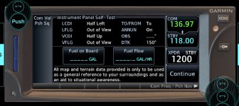
When the 430/530/650/750 etc. is booting up you will get a page that shows instrument panel self test.
Here’s a shot on 650, but they all have a page like this on boot up.

62746421-0BF0-4C06-81B4-3092748374AF.jpeg

This shows what should be displayed on you HSI or EFIS VOR/LOC indicators. LCDI, half left, VCDI half up. The localizer should be deflected half left scale and the GS bar should be half up scale. If you don’t get these indications the radio and the EFIS/CDI are not talking correctly. Easy check that a lot of people never check. Also shows which way the bearing pointers should be pointing.
When accepting pages on your 430 go slow and stop on this page and seeif your needles are indicating properly. If not, no workee!
 
I don't know whether the ARINC converter is installed..I'll have to check with the builder..if these components were installed and properly wired, exactly where should I be able to see a glide slope indicator on the D-180?

It is part of the AP box with the three knobs, I believe
 
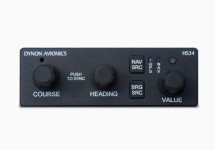
For the legacy D100/D180 all the 429 connections go through the HS34 which provides the control to the EFIS and the navigator. The HS 34 also handles RS232 connections to navcomms like the SL30 which can also drive the CDI. The guidance indications are overlaid on horizontal and vertical bars that show on the nav page or the main EFIS page (at least on my D100 and I think the D180 is the same). The nav page shows the source data and tunings etc. The HS34 lets you switch between sources (nav or GPS).
If I remember correctly the 430 connections are specifically shown in the installation manual.
Figs
 
HS34 module

You don’t have to look hard. It is on your panel.

C0418BAA-6935-4EF2-879A-DD74D33D0E32.jpeg

It appears that Dynon does not sell them any more, but you might get one from someone who upgraded to SkyView and might have one laying around. There is one as a new listing on eBay for $475 plus shipping if interested.

https://www.ebay.com/itm/224817281226?hash=item34582778ca:g:-LMAAOSwqDlh-A-C

Install manual is on Dynon’s website. It is in the D10A and D100 manuals.

If you don’t have this module on you panel, you don’t have the capability of displaying any type of vertical guidance. GS, LPV or VNAV data. Without it, it will only display lateral guidance.

Good luck.

Brian
 
Well, I do have the HS 34 panel installed and connected to my Dynon.AP74. It works to set the baro setting, select headings and courses.

If I am able to see GS info on my D-180 in the 1/3 HSI mode, would the GS indicator not be a horizontal line which crosses the vertical course deviation line? I am not seeing any horizontal lines on my HSI when shooting Rnav LPV or ILS approaches...

So, I guess there is a connection missing,or an ARINC ?? (I have no idea what that is) issue..
 
You may need to check the wiring to make sure the ARINC lines are being used. If you don't see glide slope there's a change that its either missing a connection or connected via the serial GPS communication line.

My 2 cents, the wiring is simple, take a peek and see what's hooked up.

You can also jump on the Dynon forum specific to the older D100/180 line. They are very helpful on the forum and when I had the old stuff went there often for help and was always happy to get feedback from other users and Dynon the support as well.
 
D180 config

There's also some D180 configuration settings that need to be right for it to work. There is some (rather brief!) description for this in the D-180 Pilot's User Guide on page 4-3 "CDI Glidescope Indicators" that would be worth checking. I don't have a nav radio so haven't tried it, but the display looks a little different in comparison to a traditional CDI.
 
would the GS indicator not be a horizontal line which crosses the vertical course deviation line? I am not seeing any horizontal lines on my HSI when shooting Rnav LPV or ILS approaches...
..

I’m not sure, but likely the GS will be a very short horizontal bar, displayed on a vertical scale just off to the side of the HSI. Or, it may be a short horizontal bar which goes up and down on the course arrow. Per the 180 manual, you can display GS and localizer on your main EFIS page, too. Again, GS on a vertical scale on the left side of the display, localizer deviation on a horizontal scale at the bottom. I think you enable this on the HSI menu.
Do you have a 180 manual? They’re on the internet.
 
This is from the D100 manual bur it should be the same:

CDI/Glideslope Indicators
When the EFIS-D100 is receiving CDI or glideslope information from a GPS or NAV radio, they can be displayed on the main EFIS display as well as the on the full HSI page (as described in the HSI Operation section on page 6-1). The data source is chosen on the HSI page using the NAVSRC button; the EFIS and HSI CDI/GS displays are always synchronized to the same source. There is no way to change the source on the EFIS screen.

On the EFIS page, these two items are enabled via the EFIS > SETUP > CLUTTR menu under a single item, which can be set to either CDI:N, CDI:Y, or CDI+GS.

Available Pages
The CDI is located just above the slip/skid ball when displayed, and behaves much as described in the HSI Operation section on page 6-1. The CDI needle is green when sourced from a NAV radio and magenta when sourced from GPS.
When to/from information is available, the center of the CDI is an arrow; when on an ILS, it is a filled-in square. The glideslope indicator is located to the left of the roll scale tape, and behaves much as described in the HSI Operation section on page 6-1. The GS needle is green when sourced from a NAV radio and magenta when sourced from GPS, and appears only when tuned to an ILS or a GPS source with vertical guidance.

Due to screen space limitations, turning on the glideslope prevents a left info item from being displayed on the 2/3-screen EFIS page. Additionally, at extreme roll angles, the glideslope is hidden to provide space for other screen elements.
 
Thanks everyone...I think I have enough info now to go out to the hangar and get into the menus and see what's going on I'll report back on my efforts, so please stay tuned to this thread..

I really do appreciate all of the responses...Cheers...Cheairs
 
Last edited:
Back
Top