What's new
Van's Air Force

Don't miss anything! Register now for full access to the definitive RV support community.

Exit Drag Testing

RV8R999

Well Known Member
I've been conducting pressure, temperature and drag survey tests on the stock and modified RV-8 cowling for several months now and thought I'd share some results.

Need to throw out a teaser first - Dan Horton, Sonny Wiersema and I have instrumented our RV8 cowls with Piccolo tubes and co-axial dynamic pressure probes, which Dan elegantly crafted in his usual expert manner, connected to digital water manometers. Each of us has a different cowl configuration: Dan has a plenum with modified inlets and exit, Sonny has a Sam James and I have the stock RV8 (although I've modified it with an exit nozzle and variable exit flap now). The purpose of our testing was to compare the various cowl configurations and develop comparisons in pressure recovery and a metric for cooling efficiency. We will release our findings when we are complete with all the testing....look for it - we think you'll find it very interesting and helpful!

The purpose of this post however is to report (quantitatively) the effects of adding an exit nozzle (with variable flap) and oil cooler duct on Exit Drag.

Instrumentation:
I mounted a coaxial pressure probe, which measures the dynamic pressure, in the exit plane of both the stock cowl and with the exit nozzle installed. Additionally a special temperature sensor was installed in the exit flow in order to calculate the flow density needed to determine exit velocity.

I won't go into all the details of how the sensors were configured, calibrated, or installed as those details will be included when Dan and Sonny are done collecting their data. Suffice it to say the probes were calibrated and the installation and test procedures verified through nearly 15 hours of testing.

The manometer itself was calibrated and is very accurate from 0-20" H20 which is the range we are looking for.

Note: The flow through the cowl and out of the exit is anything but steady. Heat xfer and lots of flow obstacles make quantifying the flow thoroughly very difficult. The data gathered only quantifies the flow at those particular probe positions and cannot fairly be extrapolated to other areas. The numbers I present are only valid as comparisons from one configuration to another and not necessarily representative of the true flow state throughout the cowl or exit area.

Test Procedure:
Level Airspeed sweeps from 110mph-Vmax at a PA of 3500 ft, Recording pressures and temperatures in 20mph increments.
Additionally, GPS 4 course airspeed calibration data was collected simultaneously to ensure the data reduction was accurate.

Data: Exit Total Pressure (Pitot side of coaxial probe - A/C Static), Exit Dynamic Pressure (coaxial Pitot - coaxial static), Exit Temperature, Freesream Velocity (TAS), OAT, PA, Ground speeds, Track

Configuration

Superior Xp-360, carb, FP Wood prop
2 cowl configurations:
Stock - unmodified cowl exit, OC mounted low on left engine mount fed by a 3" dia SCAT, no OC exit duct. OC inlet blocked from 7 sq " to 3.5 sq ", Stock Inlets, stock baffles, Heater inlet blocked 50%. The entire cowl perimeter, including the two halves and prop flange have been sealed with baffle material to minimize leakage and ensure the maximum amount of air flows through the exit. Exit/Inlet Ratio = .75

Modified: Same as stock with addition of an exit Nozzle with variable exit flap which reduces exit/inlet ratio from as low as .38 with flap closed and up to .70 flap open.

Exit Flap Closed:

23kxeac.jpg


Exit Flap Open: Note the axial pressure probe

2czsdup.jpg


The exit nozzle takes advantage of the sloping exit ramp in the stock RV8 configuration reducing the exit area from 47"sq to 25"sq.

As most of us know, the exit is the system throttle. The larger the exit the more mass flow we will have through the system and the cooler our engine should be. Having a large exit, while providing better cooling will also increase the exit drag as the flow velocity will be significantly slower through a larger exit area. The drag is measured as the change in flow momentum in the longitudinal direction. Flow momentum = Mass Flow * the change in flow velocity from freestream (true airspeed). The higher the exit flow velocity the lower the change in velocity and therefore the lower the change in momentum = less drag. Unfortunately, the pursuit for less drag through smaller exit area will also reduce cooling capacity. For a fixed geometry exit a tradeoff between drag and cooling must be made. For this reason I chose to fabricate an exit flap allowing me to increase the exit area to nearly stock dimensions or reduce the area to less than half. This flap is controlled by a Ray Allen trim servo connected to a switch on my stick grip with position info displayed on the VP-50 electrical system panel.

The RV8 stock exit area, is designed for the worst case cooling condition of WOT climb at Vy which means too much mass flow exists during high speed level flight leading to excessive drag. During climb I open the flap providing full cooling mass flow while in level flight the flap is closed to reduce drag - not a new concept as cowl flaps have been around forever. Additionally, I applied the same concept of exit throttle to the OC. Most folks seem to prefer blocking the inlet and some believe this is more effective than blocking the exit. This idea doesn't match theory nor experimental data. If we block the inlet to the OC we will certainly reduce mass flow and temps will increase but with a drag penalty as the air will exit the OC slower than it entered and will not aid in increasing overall cowl exit velocity. Now if we throttle the OC exit with a nozzle we will both reduce the mass flow to increase OT AND increase OC exit velocity which again reduces drag. It matters not from a purely cooling perspective which side of the OC you block but if you want drag reduction throttle the exit and accelerate the flow. My OC throttle reduces the the exit to 4" sq with an inlet area of 7" sq. OT without the OC blocked typically remained in the 160-170 range. With the inlet blocked 50% OT were in the 185-195 range. Now with the OC exit throttled to 4"sq OT are in the 185-195 range but with greater exit velocity.

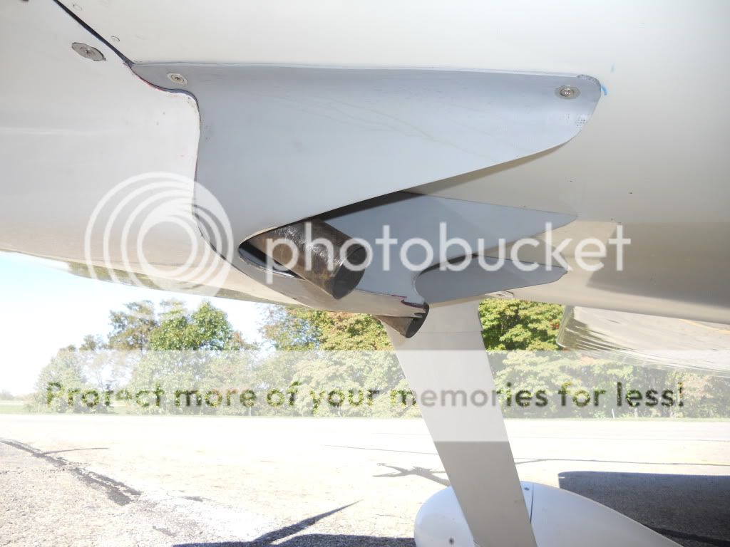
Pics of the OC exit throttle:

i2rfwk.jpg


4q1ttt.jpg


Results:
Using a fixed W/delta technique I measured a TAS increase of 6MPH with the exit flap closed and nozzle installed over the stock cowl configuration and a 7MPH increase from the exit flap open condition (the exit flap produces some drag itself when open).

Here is the data:
28ixe9t.jpg


Cooling: I'll provide more info on cooling when the full test is completed but for now I'll say the exit flap works as designed in that during climb when flap is open my Avg CHTs are just slightly higher than stock (even with the flap open the exit area is a bit smaller than stock) but during WOT level flight they avg low 300s with exit closed. A WOT climb at Vy with the exit flap closed results in CHTs rising about 20-30 deg hotter than with it open as expected.

Thanks to Dan for fabricating and sending the pressure probes and many discussions with he and Sonny along the way. The full test will be full of good information. I tried to keep the math out of this posting but if there is interest I can submit more detail on how the data was reduced.
 
Interesting - especially the part about a 6 mph gain in speed

I also have experimented quite a bit in this area on our RV-6A. As you state, I found that the reduction in inlet area increases the temperatures by reducing the air mass flowing through the system but did not make the airplane go faster. As I recall without digging out my data it actually reduced the airplane speed. I added a lot of duct work in the lower cowl and one particular configuration gave me a 4 kt increase in speed over my baseline unmodified airplane speed. Let's say 5 mph. During my experiments with a curved multipiece aluminum panel from the back of the engine to 3/16" or 1/4" below the bottom of the fuselage and two vertical panels slanted in from the sides of the cowl to the curved panel at the width of the exit I slowed the airplane down from the baseline ~2kts. This was the worst case that I remember without researching my records but anyway, this shows that a difference in airplane speed of 6kts with different cooling air flow configurations after the cooling air mass passes the engine is achievable. I tried MANY experiments in the lower cowl and and all of them failed except the configuration I described above with the addition of horizontal baffles just below the cowl split line which isolates the post engine cooling air from the area of the upper cowl outboard of the plenum (formed by baffles and the inside on the upper cowl) & valve covers and the area between the engine and the firewall. I sawed off the downturned exhaust tips and picked up a fraction of a knot there as well. I think there is probably some more speed there but I have not had time to work it over the last couple of years. The nose gear is a little bit of a complication. In my mind I think there may be an advantage in continuing the curved panel below the fuselage and curving it back up to the fuselage with a concave surface after the lowest point then fair it into the fuselage. Some flow fences may be needed at the sides of this panel below the fuselage. I think this will reduce the exit area which will probably increase temperatures sitting on the ground and flying slow. A cowl flap may effectively deal wih that limitation. I have my oil cooler mounted on the baffle aft of cylinder #4 so it outlets into the area between the engine and the firewall that I call cowl zone 3. The outlet for that air is the 3/16" or 1/4" gap between the back side of the curved panel and the bottom of the fuselage. When I experimented with this vent by opening it 1/16" it resulted in the plane going slower so it appears to be quite sensitive. The oil temperature almost never goes above 180 degrees but if I try to turn the exit air by having it follow the curved panel extension aft of the firewall with a reflex to align it with the path of flight I have to provide for a zone 3 outlet. I'm thinking now that I could just include the same gap at the rear of this new panel.

I am working on my hangar walls right now but it would be good the try an implementation before the SARL race season starts.

Bob Axsom
 
Last edited:
This is really cool data, and a well done experiment. I would be very interested in the construction details of the coaxial pitot/static probes, as well as the spreadsheets with the source data and the data reduction methods.

Thanks for the well done work so far, and looking forward to more.
 
Simple enough

Dan-

Thanks for the picture. Worth at least 1000 words. I assume that the pitot OD is << Static ID, and that the "nose" carries the pitot through, and locates the static to be concentric to the pitot tube. Then a few cross drilled holes for static.

Seems simple enough. Only marginally different from the heated pitot I made out of a surplus Cessna pitot heater, some 1/4" aluminum tubing, and a 3/4" OD tube.

If you had a dimensioned drawing for that and the piccolo tube, that would be great.
 
I assume that the pitot OD is << Static ID, and that the "nose" carries the pitot through, and locates the static to be concentric to the pitot tube. Then a few cross drilled holes for static.

That's the idea. A 0.016" wall leaves a little over 0.015" for a annular passage between inner and outer tubes. The static line taps that annular passage inside the block. Everything is a snug slip fit secured with T-88 epoxy.

2wm4412.jpg

ztgnti.jpg

sv2ux3.jpg

34ou6uh.jpg


Note to all; the probe gives you local static and total pressures. Total minus static = dynamic pressure. Use the raw numbers for calculations....or simply connect an airspeed indicator if all you want is exit velocity.
 
Last edited:
I just made heated pitot with a built-in static source that is very similar, but larger, for my rocket.
 
I am reading this with great interest, and see some real improvements within the reach of us average builders. Relatively simple mods may make some difference. Your pilot drawing also brought up a connection to another problem--an AOA pickup for the RV-12. It looks to me like a change to the tip design would allow a second, angled pressure pickup instead of static. Thoughts?

Bob
 
Ken,

Do you have a means of also independently throttling the flow either to or from the oil cooler, or have you taken data with different oil cooler exit areas?
 
Ken,

Do you have a means of also independently throttling the flow either to or from the oil cooler, or have you taken data with different oil cooler exit areas?

No and I prob won't as I sized my OC exit based on data from two southern Florida summers temps and have it tuned for those conditions. I could add a variable exit throttle to my nozzle for winter Ops. The data I've taken is with OC unblocked, 50% blocked at the inlet, 60% blocked at the exit with a converging nozzle. Both cases with OC blocked raised temps equally Under similar test conditions. Unblocked OT never exceeded 170. So for an equivalent rise in temp a converging nozzle will reduce drag through the oil cooling system through reduction in the change in momentum from OC inlet to outlet by accelerating the flow through the nozzle. If this flow is directed to the cowl exit in close proximity and parallel to exit flow it will reduce overall drag too. If it is dumped into the open area behind the cyl it prob wil
Not make a difference. My OC nozzle ejects the flow right at the opening of the cowl exit.
 
Send me your email and I'll forward to you

Spank

Someone beat you to it, thanks whoever that was!

Only 8 #'s of drag at normal cruise from the cooling? Am I reading that right?

So, is there any empirical data throughout all this to quantify drag reduction or advantages to different setups such as plenum vs baffles?
 
Ken,

Nice looking work, and well done on the testing...obviously a lot of rigor! A few questions for ya, if I may:

1. The 6-7 knots is actual aircraft speed increase, correct? (Just want to make sure I'm interpreting the graphs and your words correctly.) Looks like the throttled cowl exit increased exit velocity about 20 knots, giving you that 6-7 knot aircraft speed gain (shown as freestream velocity...am I on target there?)

2. Does the graph go to Vmax (looks like 167 KTAS) or is there more top speed data? (Or is that freestream velocity on the graph not the same as aircraft TAS?) Basically digging to see the net effect the throttled exit had on top attainable speed.

3a. How much cowl exit air velocity increase did you measure when you directed the OC exit air at the cowl exit with your OC throttled exit. 3b. Did you also measure an increase in aircraft speed with this directed OC throttled exit?

4. Do you have any more pics of the cowl flap and its actuator? Perhaps with the exit throttle removed for a good look? (If your "OPSEC" rules allow! ;))

5. Any pics of the oil cooler nozzle installed?

Really nice work...can't wait to see the full battery of tests! Thanks very much for sharing this!!

Cheers,
Bob
 
Someone beat you to it, thanks whoever that was!

Only 8 #'s of drag at normal cruise from the cooling? Am I reading that right?

So, is there any empirical data throughout all this to quantify drag reduction or advantages to different setups such as plenum vs baffles?

Remember in my OP I mentioned then necessity to be cautious of absolute values as there is so much variability in the flow it is hard to measure absolute flow values using single point probes. To do it completely would required pressure rakes spanning the exit area in both lateral and vertical planes. Temp readings would also need several probes to fully characterize the temperature variations. These numbers only provide a relative comparison from one configuration to another. The important data is showing that a significant reduction in exit drag occurs when it is throttled with an appreciation for the magnitude.

Also, the 8# is only the drag measured coming out of the exit area. Any leakage around the spinner, oil access door, cowl seems well also add to the total cooling drag. In upcoming tests I'll attempt to measure the true inlet mass flow and then subtract the exit area mass flow to determine the total leakage - the majority of which I believe exits out of the spinner area (even though I've attempted to seal this area).

As far as drag comparisons between plenum styles we may be able to extract some comparative data with respect to drag but this will be suspect to variations in probe installation locations which is hard to standardize. We will see.
 
Last edited:
Ken,

Nice looking work, and well done on the testing...obviously a lot of rigor! A few questions for ya, if I may:

1. The 6-7 knots is actual aircraft speed increase, correct? (Just want to make sure I'm interpreting the graphs and your words correctly.) Looks like the throttled cowl exit increased exit velocity about 20 knots, giving you that 6-7 knot aircraft speed gain (shown as freestream velocity...am I on target there?)

2. Does the graph go to Vmax (looks like 167 KTAS) or is there more top speed data? (Or is that freestream velocity on the graph not the same as aircraft TAS?) Basically digging to see the net effect the throttled exit had on top attainable speed.

3a. How much cowl exit air velocity increase did you measure when you directed the OC exit air at the cowl exit with your OC throttled exit. 3b. Did you also measure an increase in aircraft speed with this directed OC throttled exit?

4. Do you have any more pics of the cowl flap and its actuator? Perhaps with the exit throttle removed for a good look? (If your "OPSEC" rules allow! ;))

5. Any pics of the oil cooler nozzle installed?

Really nice work...can't wait to see the full battery of tests! Thanks very much for sharing this!!

Cheers,
Bob

Freestream = A/S TAS

My data goes to Vmax. I'm turning a Sensenich Wood prop pitched for mid-performance which results always results in a 2700 rpm limit forcing me to throttle back. Without the exit throttle I was limited to 191 MTAS. With the throttle I achieved 197 MTAS with reduced FF.

Exit total pressure changes with OC throttle were slight, .1-.3 "H2O with no more than 1mph (max) increase in speed. I'm always a little suspicious of measurements of such small magnitude.

I'll take more pics of the installations as I refine them further (works on progress).
 
So, is there any empirical data throughout all this to quantify drag reduction or advantages to different setups such as plenum vs baffles?

Dynamic and static can trade back and forth without loss in smooth flow, i.e. total pressure remains the same. Losses are introduced by separation and turbulence.....for example, with a poor shape inside a high velocity inlet. If the initial conversion of dynamic pressure to plenum static is poor, then it is not possible to have much static pressure further downstream in the lower cowl, one key to exit velocity.

Put another way, I think the plenum's contribution to drag would be indirect, a function of connecting the plenum to the inlet. The plenum itself is just a seal, as are rubber strip baffle seals.

Anyway, that's the view from the cheap seats ;)
 
Last edited:
Upon reflection, the previous post is really not appropriate for this thread. I'll leave it, but as penance I would like to bring the thread back to the important stuff.

Ken is demonstrating the effect of exit-throttling a stock RV8 cowl. The speed increase is real, and there are really only two modifications...

(1) an effort to seal the lower cowl volume, and
(2) a variable exit area.

Note the words "variable exit area", not "cowl flap". Bad nomenclature can misdirect your thinking. There's no attempt to stick an air dam into the freestream and generate a low pressure area behind it, thus somehow sucking air through the cowl. Look close. When open, there's no more rear facing area in Ken's very clever execution than with the stock exit.

I'll be incorporating the idea into my next exit.
 
Last edited:
Freestream = A/S TAS

My data goes to Vmax. I'm turning a Sensenich Wood prop pitched for mid-performance which results always results in a 2700 rpm limit forcing me to throttle back. Without the exit throttle I was limited to 191 MTAS. With the throttle I achieved 197 MTAS with reduced FF.

Exit total pressure changes with OC throttle were slight, .1-.3 "H2O with no more than 1mph (max) increase in speed. I'm always a little suspicious of measurements of such small magnitude.

I'll take more pics of the installations as I refine them further (works on progress).

Ken, Copy all, and it all makes good sense. Understood about the speed vs prop RPM, and that makes the speed gain even more impressive, IMHO! Concur on the oil cooler exit throttle results...but if that is repeatable, it is worth the effort, for sure. Just finishing my baffles (corner baffle OC mount), and dreaming up ways to unashamedly copy your work! I figure Bob Axsom is already in his shop doing the same! ;)

Upon reflection, the previous post is really not appropriate for this thread. I'll leave it, but as penance I would like to bring the thread back to the important stuff.

Good call, as your thread has been nicely focused. However, Landfill (Sig)...recommend you start your own thread to ask that question (as you did of me via e-mail). Would be a good discussion (plenum vs baffles)!

Ken is demonstrating the effect of exit-throttling a stock RV8 cowl. The speed increase is real, and there are really only two modifications...

(1) an effort to seal the lower cowl volume, and
(2) a variable exit area.

Note the words "variable exit area", not "cowl flap". Bad nomenclature can misdirect your thinking. There's no attempt to stick an air dam into the freestream and generate a low pressure area behind it, thus somehow sucking air through the cowl. Look close. When open, there's no more rear facing area in Ken's very clever execution than with the stock exit.

I'll be incorporating the idea into my next exit.

Quite clever indeed, and I'll be very interested to see your treatment of the concept (all the while cyphering how to play that into a 6 cowl with no recessed exit ramp). In the short term, the exit extension and throttle looks like a good first term experiment with the remaining winter mod time this off-season.

Quick question: In #1 above, by sealing the lower cowl volume, are you referring to the baffle-material seals at Ken's cowl half seams and prop flange, or are there other seals in play between the upper and lower cowl areas (like Bob Axsom has done)? Just trying to keep the picture clear. Thanks!

Cheers,
Bob
 
Quick question: In #1 above, by sealing the lower cowl volume, are you referring to the baffle-material seals at Ken's cowl half seams and prop flange ...

Yes.....half seams, behind the prop flange, and around the firewall perimeter.
 
Ken,

This is a great experiment. I'd be curious is you're planning to do any tuft-testing to look at how your design is affecting airflow?

There have been some videos posted that indicate that the area around the cowling exit can be very turbulent. I noticed with my originally stock cowling exit that there was a lot of wear occurring at the corners where the cowl joins the firewall. Hinge eyelets were breaking off and paint was cracking. I attributed this damage to flexing of the cowl exit due to turbulence.

I later reinforced the bottom of the fiberglass exit with foam to make it stiffer, and extended the cowl "lip" aft of the firewall about 2". No more cowl damage since. I also added some flow-straighteners inside the cowling ahead of the firewall. When I did tuft-testing (using a cheap digital video camera taped to a wheel pant) the tufts all pointed straight back with no hint of reverse flow.

I'm wondering if some of your speed gain could be the result of decreased drag associated with the new exit geometry, as opposed to acceleration of the outflow?


certainly a strong likelihood for conducting tuft testing. I have a Contour HD with a mount I adapted which can easily be attached anywhere a #8 screw lives (lower wing root fairings for example).

tufting with and without the nozzle would tell a tale for sure. Look for it in the near future. Good suggestion!

I'd really like to conduct tuft testing INSIDE the cowl. Seeing those little yarn pieces pointing up towards the spinner I bet would help inspire the collective VAF brain trust to devise better ways to deal with it. Between Dan, Tom and I we only have 2.5 brains (that I'm aware of) working on the problem....
 
Allan, Is this about what you are describing???

This is my exit fairing with extended sides and a center body flow straightener. I have been wanting to tuft test, but haven't gotten to it. Oil drop testing does show some very nice streamlines around the exit with no reverse flow areas as you get on the stock exit.


airplanetransfers039.jpg


More pix in this thread http://www.vansairforce.com/community/showthread.php?t=77090&highlight=cowl+flap&page=7

Post number 65. Picked up 5 - 6 KIAS (verified with the NTPS three leg test runs) and lowered CHT's about 20 F.
 
Last edited:
ME TOO!

I washed the plane today and got under it to visualize what I was thinking of and it will not work exactly as I had thought but what you have done is doable even with the nose gear support structure. 5 - 6 kts WOW!

Bob Axsom
 
Gary, can you explain why your fairing works?

You added a large radius to the lower edge of the firewall. Ever consider a test flight with just the radius addition, no fairing shell?
 
Dan, What I was trying to do primarily was eliminate the reverse flow that happens in the corners where the cowling outlet meets the firewall. I had noticed (via studying oil drop trails) that there was actually reverse flow occuring in these corners. Obviously that could not be good.

A simple fairing that filled these corners and extended the cowl outlet back prevents the high energy free stream flow from backflowing into the corner and gives the exit air a chance to straighten as it comes out that corner, accelerate and blend with the free airstream. This simple fairing netted 4 KIAS (and 20 degrees less CHT).

My thought with the center diffuser was to divide the airflow as it comes out of the cylinder baffles from the left and right sides and smooth and direct that flow (de-conflict it so to speak) out the exit. In addition it was intended to decrease exit area and thus provide some exit area throttling. I already had relatively low temps (oil and CHT's) so I was looking for drag reduction.

As part of this, I made an effort to de-clutter the exit area, primarily by streamlining the pipe hangers (sorry Larry, your "stock" hanger system is kinda klunky).

Now with this effort, oil drops show very good exit streamling, temps are way down (cruise CHT's 320 and below, OC always partially blocked to get 185)

I intend to begin to reduce exit area further in an effort to reduce mass flow and drag further. Just not sure how yet with this exit configuration - maybe a fatter center body.

The firewall bottom radius was already in the airplane when this exit fairing was added (the firewall radius fairing was last winters project).
 
Last edited:
Bob, Go check out a Lancair Legacy cowl exit. They have these same kind of exit blending fairings. Also Google F1 (Formula 1) "chimmneys". You will see how those guys fair engine compartment/exhaust exits. No sharp corners and they are spending big $$$ in wind tunnels. See here http://www.f1-country.com/f1-engineer/aeorodynamics/f1-aerodynamics.html

No doubt in my mind it will work on your A model.

Next on my list (before the eastern SARL races) are the elevator horn/HS end fillers as you have done...thanks for that one!!
 
Last edited:
Dan, What I was trying to do primarily was eliminate the reverse flow that happens in the corners where the cowling outlet meets the firewall.

Yep. I just eliminated the corners, but doing so is easier on the -8. However, I suspect if exit velocity was high enough the corners would not matter.

20icuf8.jpg


This simple fairing netted 4 KIAS (and 20 degrees less CHT).

Think about that; a reduction in drag despite an increase in mass flow....... which brings us back to why does it work.

The increase in mass flow should slow the airplane, so you either got a large increase in exit velocity, or a large decrease in form drag, or some of both. So which is it? There's the point....can we convince you to instrument and measure so we learn not just results, but why?

BTW, perhaps we should consider a change in nomenclature. Reverse flow is probably a misleading term. Turbulent flow is probably closer to the truth. Oil drop tracks and similar are two-dimensional, while the reality is three-dimensional.

As part of this, I made an effort to de-clutter the exit area, primarily by streamlining the pipe hangers

Amen brother.

The firewall bottom radius was already in the airplane when this exit fairing was added (the firewall radius fairing was last winters project).

And it by itself brought no change?
 
Yep. I just eliminated the corners, but doing so is easier on the -8. However, I suspect if exit velocity was high enough the corners would not matter....


BTW, perhaps we should consider a change in nomenclature. Reverse flow is probably a misleading term. Turbulent flow is probably closer to the truth. Oil drop tracks and similar are two-dimensional, while the reality is three-dimensional.

Dan,

It appears in your photo that the oil streaks are streaming straight back on the fuselage. Does it do the same on the ramp area? I noticed on my 8 that the oil drops were actually moving at an angle across the ramp (maybe 20°) which seemed an obvious indication of something other than unidirectional exit flow.

I'd agree that "reverse flow" is imprecise since turbulence is 3D. Maybe a better way to say this is that there are local areas where the net flow vector is pointing in the direction of flight? Some of the video's clearly show yarn tufts pointing forward (toward the engine) as I recall.
 
Dan, the firewall bottom radius is stock on RV-8s.

It's P/N F-867A, made of .020 or .025 aluminum. The bend radius is 7/16".

Dave
 
Dan

Yep. I just eliminated the corners, but doing so is easier on the -8. However, I suspect if exit velocity was high enough the corners would not matter.

Agree, high velocity would eventually overcome stagnation/turbulence in this area, but I don't think it is nearly high enough on a standard -6 exit.


Think about that; a reduction in drag despite an increase in mass flow....... which brings us back to why does it work.

The increase in mass flow should slow the airplane, so you either got a large increase in exit velocity, or a large decrease in form drag, or some of both. So which is it? There's the point....can we convince you to instrument and measure so we learn not just results, but why?


I think it is most the first (increased exit velocity) and some of the second (reduced form drag).

I would consider instrumenting. My Fairing comes on and off fairly easily (do have to de-cowl though). Didn't volunteer to be part of the effort as my set-up is pretty non-standard: stock inlets, sealed to modified SJ plenum, ducted OC to this exit fairing. Agree that my root cause theory is pretty subjective with no data, other than fairly carefully documented net results.

BTW, perhaps we should consider a change in nomenclature. Reverse flow is probably a misleading term. Turbulent flow is probably closer to the truth. Oil drop tracks and similar are two-dimensional, while the reality is three-dimensional.

Agree, not sure that the flow in this region is totally "reverse", but it certainly is turbulent.


And it by itself brought no change?

Some, but the increase got lost in the clutter and shoddy documentation.

This hobby is getting engrossing!
 
Last edited:
I wonder how much an after fairing, something like Vetterman has, would change things on
this setup???

airplanetransfers039.jpg
 
Mike, Thought about that and have looked pretty close at all of the Vetterman and Elippse (miss that guy!!) versions. My subjective opinion is that most of the gain realized with that set-up comes from reduction of the same pesky turbulence drag at the corners of the exit that my version also accomplishes.

I was hoping to do the same thing as the Vetterman fairing but with what I thought was an easier fabrication.

I also think that smoothing of that corner flow is where the big gains lay, and from here on out it will be much smaller returns on effort. The bigger after body would be a way to smoothly reduce exit area and begin to "exit throttle" mass flow. Hmmmm...

All IMHO of course.
 
Last edited:
I have been sitting here thinking about what may be going on with your setup, and have come up with a couple thoughts.

Think about how a NACA duct works, the sharp edge of the opening causes the boundary flow to "trip", and fall into the duct opening.

Your fairing extension is lengthening the line where the airflow trips over the edge of the outlet, thus lessening the force at any particular location. I suspect someone who is trained in aerodynamics can elaborate a bit better, but it would seem that the same force applied over a greater area may have something to do with it.

As you said, Paul Lipps surely would have been able to give some insight here.

I am thinking of his discussions on the Coanda effect ------ and how it may apply to your adding an after fairing.

May be time to revisit some of the thoughts here.

http://www.vansairforce.com/community/showthread.php?t=58643&page=6
 
Question for Garry Reed

I have looked at your fairing and the references you provided. I see what you are doing with the external vertical surface, the center vane, the cutouts around the pipes and everything I see makes perfect sense. I am curious about the two scalops in the trailing edge of the horizontal part of your fairing they are too inconsistent with the basic smooth lines to be accidental and they obviously will affect the flow coming across that high pressure area and rising into the void. I suspect that is your intent and it looks just right. Did you try different shapes on this edge? Another observation that I should keep to myself, since we are in the same racing class I believe; I can easily visualize the effect of the center vane and it seems to me that this would be enhanced by extending it back farther than the tapered side dams.

Bob Axsom
 
Last edited:
I think it is most the first (increased exit velocity) and some of the second (reduced form drag)....I would consider instrumenting.

Please. You have something interesting going on. Increased mass flow (evidence being the lower CHT values) and reduced drag are not normally found together. It is worth sorting out (what does what, the why) because your next trick is a mass flow reduction for cruise and/or racing.

An exit velocity measurement as Ken illustrated will tell much of the tale. Do one with the exit fairing and firewall radius, one without each piece, and one without both.

Some, but the increase got lost in the clutter and shoddy documentation.

I thought so.

Consider the measured exit velocity values Ken graphed in post #1, over 50% of freestream for the stock exit size and about 66% for a throttled exit. At the magic 200 KTAS you would have 130 knots in the exit.....not a great place for a square corner.
 
Bob

I wanted to keep as much horizontal "floor" in the fairing as possible to acheive as much airflow fairing as possible. So for that reason, I tried to keep the radius close into the exhaust pipe as much as possible while also keeping the curve smooth and asthetic.

When I got out to the end, I had some width left to transition at the end. What to do? Cut it off flush?? round it off? I just picked the scalloped, bat wing curves because it looked cool (I thought) and is maybe aerodynamic (works for bats!).

My original design had an overall longer fairing and an even longer center bluff body. I trimmed it all shorter as I went, again basically to get it into asthetic proportion and be faired to the eye. Longer might be better, especially if you are going for a wider center body to reduce exit area more (or to fair more of the nose strut in the case of an A model). Check this example for long and faired http://aerochia.com/parts_images/ES_3_lrg.jpg

Dan, I think that the explanation of how mass flow could go up and still see a decrease in drag lies in just how draggy the stock 6/7/9 exit is. When could you send me a loaner probe??
 
Last edited:
Bob,

This will help everyone visualize the A model problems.


I am consulting some good advise on the gear mount and think
I have a good solution to the problem.
I do like what Gary has done.
I did lose the holder for the cowl halves. This was a one time flight on
this setup and now have a 6" x 10" plate that goes over the split in
the seam.
Not taking very many readings just trying to get the oil temp down
and velocity up in this area.
 
Yep There's the complication

I think Mr. Reed has a configuration that will work on our A's though. He has staggered the location where the high speed wind interfaces with the low speed wind coming through the cowling in a way that I think accelerates the low speed wind (when it is coming by the NLG support structure I don't think it is all that fast) by friction from one direction only. Then it is blended with the wind side wind gradually to the end of the fairing. I think the center vane probably helps keep the flow linear and I think it would do it even better if it extended back maybe a foot aft of the side fences. The scallop points have to be deflecting the wind coming across the bottom and may be setting up two small vortices which intuitively I feel is probably better than dragging the equivalent of a half round plate throught the air at some positive angle of attack. Still thinking but I am leaning toward a metal implementation right now.

Bob Axsom

The only problem I see in this is that anytime freestream flow is the impetus for accelerating low speed air, drag occurs as the net change in momentum is decreased. The low speed air affects the high speed air as well - no free lunch. For drag reduction, the acceleration of the exit air must be accomplished through work done on the system, heat xfer, or an area change. From a pure cooling point of view freestream could be used in many different ways to help increase mass flow.
 
Bob,

Letting out race secrets but.
After removing the device that holds the two cowl halves
together the air flow was straight.

With the holder in place the air would move straight back
on the outside and would go back toward the exit in the middle.

Just looking at the oil trail here for the novices.:eek::rolleyes:

I will put a fairing on the back side of the NGL to see if I can
speed the air up here.

My .05
 
The only problem I see in this is that anytime freestream flow is the impetus for accelerating low speed air, drag occurs as the net change in momentum is decreased. The low speed air affects the high speed air as well - no free lunch. For drag reduction, the acceleration of the exit air must be accomplished through work done on the system, heat xfer, or an area change. From a pure cooling point of view freestream could be used in many different ways to help increase mass flow.

This could be where the exhaust pulses could be used to speed up the exit air prior to hitting the outside free streaming air. Would probably require a bend in the pipes in the example shown, and having them cut a bit shorter.
 
The only problem I see in this is that anytime freestream flow is the impetus for accelerating low speed air, drag occurs as the net change in momentum is decreased. The low speed air affects the high speed air as well - no free lunch. For drag reduction, the acceleration of the exit air must be accomplished through work done on the system, heat xfer, or an area change. From a pure cooling point of view freestream could be used in many different ways to help increase mass flow.

I'm just repeating the above so maybe ya'll will read it again.....
 
I suspect the freestream air is affected by th stock outlet

The airplane is moving through the air and work is being done inside the cowl. How the air is routed inside the cowl varies from airplane to airplane and after running a lot of experiments I personally doubt that any of us knows exactly how each unit of air moves from the inlet to the outlet. I have shared my experiments as you are doing and I'll bet you guys come up with some really good math that will allow the prediction of things as others have done before us. I am convinced that I have the best internal flow I can get for my airplane velocity. At the cooling air outlet in the stock configuration there is internal air that is moving in the direction of the airplane relative to the outside air but it is being released out the back so at that point it is certainly not traveling as fast as the airplane. The local outside air is being accelerated in the direction of the airplane as well because of skin friction but probably not as much as the inside air. The skin friction adds heat to the outside air but not as much as the engine and friction heats up the air traveling through the cowl. The immediate curiosity in my mind is, is more tubulance and drag created when these two bodies of air come together around the entire outlet perimeter at one point than if the combination is in line with the exhaust pipes at two small points and some small area action takes place to stabilize those interfaces and and gradually spreads vertically and horizontally to the remainder of the interface. I don't know the answer to that but Mr. Reed's results are compelling enough for me to think about giving it a shot.

Bob Axsom
 
Last edited:
Bob

I think that you are looking for way to much voodoo in this design. My intent was simply to

A) Reduce turbulence at the cowl exit

and

B) Eventually use the center body as a means to try to tune exit area as a means to throttle mass flow.

I think it does a great job with A. The increased flow rate (evidenced by increased cooling) along with a reduction in drag (I know those two are typically diametrically opposed but I conjecture that the reduction in drag at the outlet via reduction in flow turbulence flow is greater than the increase in drag from increased mass flow rate, more careful testing will tell that tale).

I hope it will help eventually with B.

Beyond that, there may be a small coanda effect happening because of the shape of the firewall/bottom round down, but I certainly would never claim that it produces a propulsive effect. As Ken says, no free lunch.

Look at it for the turbulence reduction and move on.

Have fun
 
Gary I guess I didn't explain myself clearly

What you describe is exactly what I think it is that your outlet provides in the way of improvement. I think you guys are so tightly wound up around the idea of measurement of pressure differentials and flow of the mass of air through the system by measuring little points in the system you apparently lose sight of the fact that the simple reduction of turbulence at the outlet reduces drag which plays a critical part in the:

speed = thrust - drag

equation.

Did you think that I suggested anything else. It has been suggested by someone with an RV-8 that is MUCH faster than our RV-6A that the the heat added to the air in the cooling process could provide some thrust but I have never claimed that. My focus is and has always been on drag reduction and I think the outlet geometry you have created does that. Sorry, you are the one that let the cat out of the bag. 5 to 6 mph increase in speed in deed! If I can get 0.6 kt and break 185 KTAS for the first time I would be more than happy.

Bob Axsom

No springs here... nice cool beer on a Friday afternoon waiting for my new CATTO prop to arrive.

Bob - what do you think creates the turbulence? Why does a sharp corner do that? It is precisely because of a delta in flow velocity. The fast air meets the slow air in an abrupt manner and quickly disorganizes. Measuring the internal parameters helps us understand better how we might optimize a particular solution. Without data we are stuck with a trial-n-error process which may or may never lead to any success - any success gained would have been done so without the basis in knowledge and therefore not easily adaptable to other configurations.

My humble .01
 
Exactly!

It would be pretty hard not to recognize that the turbulence is caused by the combination of different air forces. You can try to get your head around it academically or you can just do it and go with what works. I don't care if I can't construct a knowledge model to base success on. A concept proven by testing is good enough for me.

Bob Axsom
 
Back
Top