What's new
Van's Air Force

Don't miss anything! Register now for full access to the definitive RV support community.

Rotax Electrical Charge System & Ducati Regulator

AJSWA

Active Member
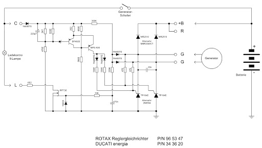
Reading up on a number of forums and web sites trying to get a good understanding of the operation of the Rotax 912 electrical charging system, there seems to be at least a couple of views of how the regulator regulates the charging system output.
Can anyone confirm how the Ducatti regulator controls the excess charging capacity?
Does the regulator convert the excess charging capacity to heat energy?
When does the regulator create the largest amount of heat?
Is it when it is supplying maximum Charging capacity to supply electrical demand?
Or when the regulator is regulating excess generator capacity? (i.e. when the battery is fully charged and there is minimal electrical demand say 1 or 2 amps perhaps )
 
The regulator is simply a switch that turns the charging system on and off. Switching is controlled by the regulator "C" pin. If the voltage to the C pin is above 3 volts the regulator will switch on, when the voltage to this pin exceeds 14 volts, it turns off. The gating power to switch the regulator on, comes from the C pin and is referenced to the regulator case (ground.)

When not charging there is no appreciable heat generated. Heat is proportional to amps out.

(Output current ) times (the voltage drop of the internal full wave SCR bridge)= heat dissipated
 
Last edited:
Motorcycle regulators work by using SCRs or MOSFETs to dump the current from the generator when the system voltage is reached. The current continues to flow, but because the voltage drop across the SCR or MOSFET is typically a fraction of a volt, very little power and heat is dissipated in the regulator while it is dumping the current. A good mechanical equivalent is if you are pedaling a bike at a constant rate and suddenly remove the chain, you keep pedaling but no power is delivered.
 
Great questions Andrew - I'd like to know the answers as well. In an effort to prolong the life of my second ROTAX regulator, I typically turn OFF my unnecessary electrical loads (e.g., strobes, nav lights, and landing light) prior to engine START and while idling / taxiing on the ground. Everything gets turned ON just prior to adding takeoff power. Right after I clear the runway upon landing, I then turn OFF these unnecessary loads. I have heard that: 1) the battery is being deleted when the engine RPMs are low and numerous electrical loads are present (i.e., typical for a generator system), and 2) the ROTAX regulator runs HOT when the engine is at high RPMs with little electrical load. I, too, am curious as to whether my efforts are of any value or are merely prolonging the inevitable.

ps -- I relocated my second regulator to inside the cooler cockpit per Van's recommendation.
 
Does the regulator convert the excess charging capacity to heat energy?
No, it does not. The output of the dynamo is an AC sine wave. The regulator allows only a portion of each sine wave through. The part of the sine wave that does not get through does not make heat because there is no current flowing.
When does the regulator create the largest amount of heat?
When the maximum load is connected.
 
I've actually had a Rotax / Ducati regulator apart.

There's really only two Permanent Magnet Alternator regulators: Shunt and Series.

It's a shunt regulator. When the voltage gets too high, it shunts the excess. This doesn't create as much heat as you'd expect because the voltage is very low, so even though the current is high, the wattage is low. Most of the heat is actually in the coils, not the regulator. For the regulator, technically it creates the most heat when the current out of the alternator is low, but the RPM is high (it has to do the most shunting).

But the regulator does something else, it's also a rectifier, converting AC to DC. This creates heat as well. The heat from here is 100% based on load current, so the higher the load, the hotter.

So there's no single answer. It creates heat when low load and heat when high load, and the max point is likely in-between.

If you really want to get in depth, here's an intresting forum discussion on regulators:
http://www.apriliaforum.com/forums/showthread.php?240785-Facts-about-shunt-based-regulators
 
Actually there are 3 types of dynamo regulators, shunt, series, and switching. A switching regulator does not shunt (short out) or add series resistance. A switching regulator shuts the current off (opens the circuit) for part of each AC cycle.
Lamp dimmers installed in homes operate on the same principle. If a lamp dimmer shunted (shorted) excess current, a circuit breaker would pop. If a lamp dimmer added series resistance, it would get hot. It does neither.
I looked at the apriliaforum forum. The post titled, "Facts about shunt-based regulators", are not facts at all. Instead it is based on a misunderstanding of electricity.
HERE is a website that provides information about the Rotax dynamo and regulator and discusses experiments and testing done by a college professor. Here are some quotes:
The regulator losses have been measured, and are proportional to the output
The Rotax regulator is not of the shunt or series type.
The reason that the regulator gets hot is because solid state devices are not perfect conductors. When current flows through them, heat is made.
Mike Miller is knowledgeable. Listen to him.
 
) 1) the battery is being deleted when the engine RPMs are low and numerous electrical loads are present
That is true. Since the charging system is not supplying much, if any, power at low RPM, shutting off electrical loads will not benefit the regulator.
2) the ROTAX regulator runs HOT when the engine is at high RPMs with little electrical load.
NOT true. If the regulator gets hot under those conditions, it is due to its proximity to hot objects.
Ways to keep the regulator cool are:
Reduce its electrical load.
Cool it with convection (moving air) or conduction (heat sink). Using heat conductive paste will help with conduction.
Mount it in a cooler location.
 
Joe,
As someone that has spent about 100 hours in the last 6 months playing with PMA's, I can tell you that they are very complex and don't act like a wall circuit at all. They saturate with current, and thus shorting them out to reduce their power is actually a pretty neat way to regulate them. It makes no intuitive sense at all until you have a really solid grasp of magnetics. I thought I understood what I was getting into when I started too and then reality smacked me down ;)

A series regulator disconnects the input from the output when the voltage gets too high. The issue? When you release a highly inductive source like a PMA, the voltages get HUGE, like 1000+V. So now you need something to deal with that. They also get hot because all the current has to go through FETs or SCR's all the time and now you have more loss at high load. In my tests, series regulators get hotter than shunt ones, although they are nicer to the coils of the PMA.

A switching regulator is totally different. This takes any voltage and any current and converts it to the voltage you want. It's really efficient, but nobody has an affordable one of these yet. The issue is dealing with huge currents and voltages. At low loads you need to be able to take 600V and 100mA and make it 12V and 5A. But you also need to take 14V at 40A and make it 14V at 40A.

Respectfully, the professor is wrong. Look at the fact that the two coil inputs go right to the battery through only a diode. There's nothing to block the output of the PMA from getting to the battery. Thus, not a switching or series regulator. Those two SCR's from the coils to ground which are switched on when the voltage gets too high? A clear sign of a classic shunt regulator.
 
Last edited:
Hi Joe
You may find the following link of interest, it seems to back up what you say. The 2 SCRs form part of a full wave bridge rectifier and are switched on when sense terminal is below required voltage allowing the rectified generator output to the battery. Once the voltage reaches the required limit the gate signal to the SCRs is turned off, the SCR stops conducting as the AC current waveform goes through zero and the bridge is inhibited. When the voltage falls back within limits the SCRs are turned back on and the bridge can allow current to flow to the battery again. The whole sequence repeats at high speed and the on / off pulses average out to the required voltage.

http://contrails.free.fr/elec_ducati_en.php

Mike
 
Last edited:
Below is a Schematic of the Ducati rectifier/regulator.
The two SCRs turn on when the voltage gets too low.
The two SCRs turn off when the voltage gets too high.
When the SCRs are off, no current can flow in the dynamo coils.
There is no shunt.
Link to clearer picture
Rotax%2BRegulator.jpg
 
Well,...... i'm not surprised there is plenty of discussion, especially after trolling heaps of web sites looking for answers. There are plenty of discussions on most of the various 912 powered aircraft forums, particularly around regulator failures. There are various and conflicting explanations. (I haven't experienced a regulator failure as yet. I've also relocated our regulator to under the parcel shelf as per the Vans mod. I can reach the regulator whilst in flight to feel the temperature and it seems to remain a fairly constant temp (to feel) from around 5 mins after lift off and up to 3 hours of constant cruise RPM)

What limits the current output of the charge system at max RPM?

So, what would happen if you installed 2 Ducati regulators in parallel?

Would it reduce the heat load on the rectifier regulators caused by the high current flow when the charging system is under max load demand?

Would the 2 regulators interfere with each other or the stators operation?

Would this possibly allow the maximum stator operational output of 80% (i.e. 18 Amps) to be exceeded?
 
The above link does not work.
What limits the current output of the charge system at max RPM?
The SCRs shut off part of the dynamo current once each AC cycle or about 500 times per second.
So, what would happen if you installed 2 Ducati regulators in parallel?
I do not know. They could fight each other or one might do all of the work. It is feasible, but maybe not practical, to install another independent electrical system to power certain loads like exterior lights and fuel pump. Reducing current from a regulator will reduce its temperature. Two regulators would not affect the stator (dynamo) operation.
The 80 percent dynamo limit has been arbitrarily set. The real limit is temperature of the insulation on the windings. If the windings are kept cool, the dynamo can operate at 100 percent indefinitely.
 
I guess I am partly assuming heat is mostly the reason for failure of these regs as I haven't heard of vibration being another cause up to just now. I struggle with that as it's an epoxy type encapuslated assembly. I would have thought vibration would have to be pretty bad throughout the aircraft as well. Or is it some kind of resonance within the regulator or something else?
I'm exploring options for the most reliable electrical system that is capable of safely handling a continuous load of say around 10 to 12 Amps, hence my questions regarding heat and regulation method. As opposed to the Ducati reg the write ups and reports from other forums and sites seem to favour the silent hectic regulator as being a more robust and possibly more reliable regulator. There probably aren't nearly as many of them in service to properly compare their durability as yet.
I don't think I would be brave enough to experiment with multiple regs on the Rv12 with all its electronics, things could get very costly very quickly if the smoke escapes from any of those electronic boxes!:)
 
Back
Top