I have searched for quite awhile and have not found many pictures of installations of this primer system.
Can builders supply some pictures of the primer installs? (Most posts that I've found, have links to pix that are no longer active)
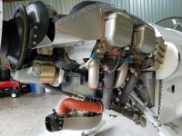
- I've seen one picture of a solenoid mount to the firewall next to the Gascolator. Seems like a good location. I've read posts that say they have mounted to an adjacent engine mount bar.
- Then there's various methods of connection from the solenoid to the Gascolator. Copper vs. SS hardline, flex hose.
- Have not found any good pix of line runs from the solenoid to the cylinder head ports. There's discussions of running the lines along the sump, or attached to the inlet runners. And some discussion on running lines on top of the engine. I have the copper tubing that came with the Van's kit.
- I've seen discussions on how many cylinders to run the lines to. Ranging from 1 to 4. I'm using the #3 lower port currently, as the sensing port for the MAP sensor.
- Is there any Van's installation instructions, other than the very limited paper that's in the solenoid box? Is there any guidance from Van's on the installation of the system?
I would appreciate any installation pictures that builders may provide. PM me for my email address if you might have pictures you could provide. They'd be worth 1000 words!
Thank you,
AC
Can builders supply some pictures of the primer installs? (Most posts that I've found, have links to pix that are no longer active)
- I've seen one picture of a solenoid mount to the firewall next to the Gascolator. Seems like a good location. I've read posts that say they have mounted to an adjacent engine mount bar.
- Then there's various methods of connection from the solenoid to the Gascolator. Copper vs. SS hardline, flex hose.
- Have not found any good pix of line runs from the solenoid to the cylinder head ports. There's discussions of running the lines along the sump, or attached to the inlet runners. And some discussion on running lines on top of the engine. I have the copper tubing that came with the Van's kit.
- I've seen discussions on how many cylinders to run the lines to. Ranging from 1 to 4. I'm using the #3 lower port currently, as the sensing port for the MAP sensor.
- Is there any Van's installation instructions, other than the very limited paper that's in the solenoid box? Is there any guidance from Van's on the installation of the system?
I would appreciate any installation pictures that builders may provide. PM me for my email address if you might have pictures you could provide. They'd be worth 1000 words!
Thank you,
AC