What's new
Van's Air Force

Don't miss anything! Register now for full access to the definitive RV support community.

Weird sag mechanical fuel pump vapor-lock issue?

BruceMe

Well Known Member
SOLVED: Weird sag mechanical fuel pump vapor-lock issue?

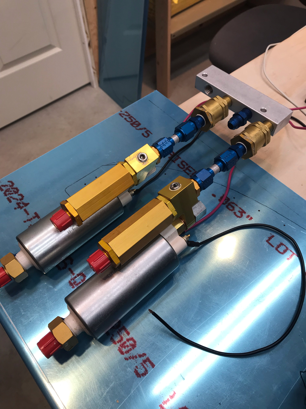
I have a recently overhauled IO-320. I'm in break-in and my power settings are high 25"/2500. OAT is about 50F, CHTs are running nice and evenly around 380-400F. After about 20 minutes of flying, the engine starts to sag. I watched it carefully and noticed the fuel pressure dropped bellow 18psi. When I pop on the electric pump it jumps back to life and so does the pressure (25-30psi) for a few minutes. Then about 5-10 minutes later, same thing.

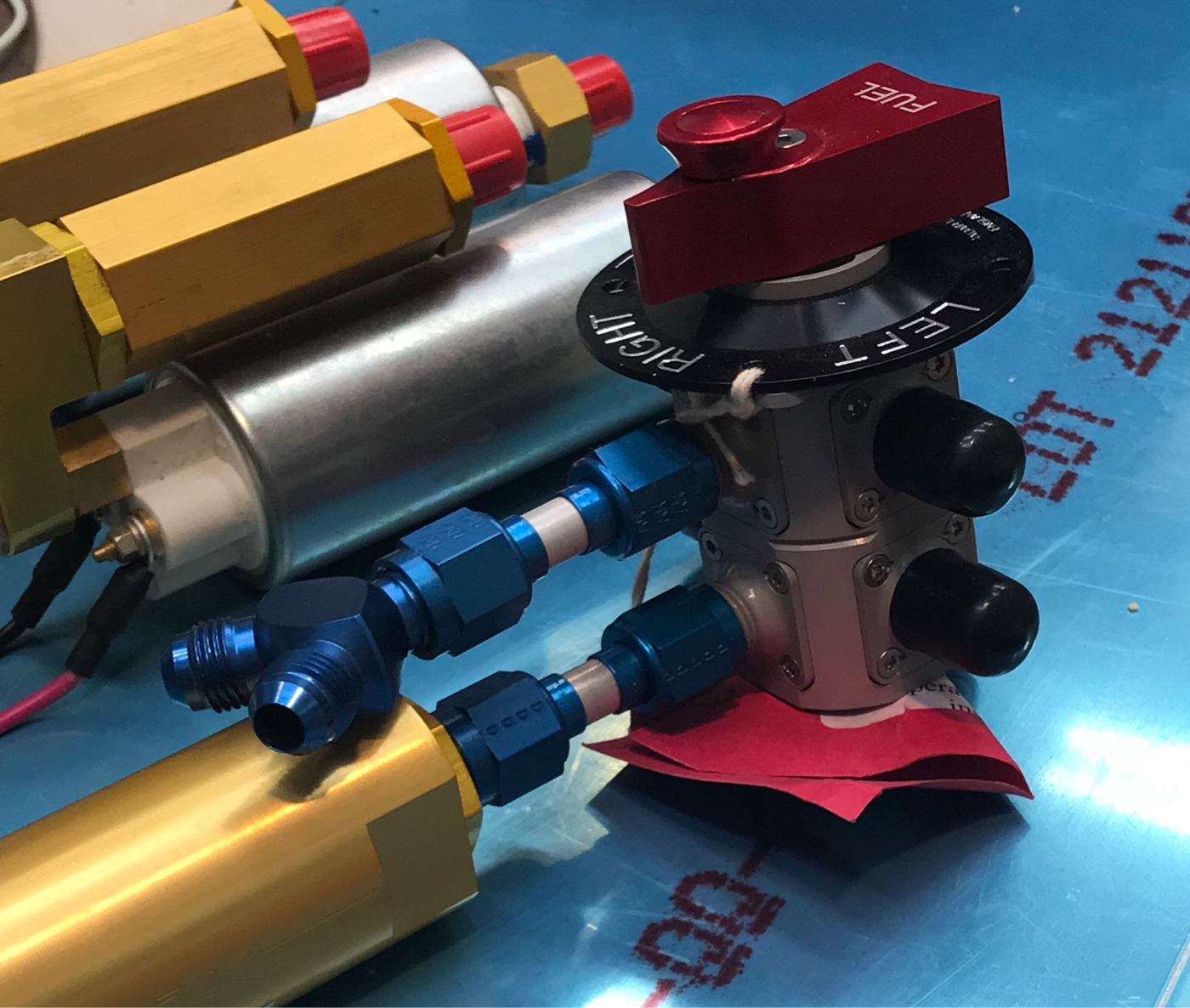
I also re-routed the fuel return back to the tank (duplex valve), the preferred method, if that's an issue with low pressure.


I noticed my mag cold-air tubes weren't well secured and blowing off to the side and not down the accessories which includes the fuel pump. Is it possible the fuel is boiling in the pump and hindering the pumps ability? Is that a thing? I'll secure the blast tube and fly again (over the field) and see if that fixes it.

-Bruce
 
Last edited:
inadequate data...

You didn't mention what kind of fuel delivery system you have. If it's conventional Bendix style injection, why do you have a duplex valve/return line to the tank?

Charlie
 
Bendix RSA-5

it drops as low at 15psi. It's not missing, it's sagging. Like it can't deliver enough and leaned the mixture. Also manifold pressure rises about 1" when this happens.
 
Bendix RSA-5

it drops as low at 15psi. It's not missing, it's sagging. Like it can't deliver enough and leaned the mixture. Also manifold pressure rises about 1" when this happens.

Bendix injection normal flow: boost pump>engine pump>throttle body>spider>injectors (no return line).

Why the duplex valve & return line? Is there a separate mechanical pressure regulator thrown into the mix, like auto-style electronic injection?

Charlie
 
Bendix injection normal flow: boost pump>engine pump>throttle body>spider>injectors (no return line).

Why the duplex valve & return line? Is there a separate mechanical pressure regulator thrown into the mix, like auto-style electronic injection?

Charlie

Pump -> regulator -> TB -> Spider - Injector

regulator has a return line

pump has the built in regulator, it's an older-style airflow performance ('05 ish)
 
Last edited:
It's also too rich

I should note, I think the TB is setup for an O-360 cause it's slobbery rich all the time. If I go full rich, the engine will load up and die at idle any temperature. There doesn't appear to be any mixture adjustment on the TB that I can find, I could just change the stops. At full 80% power (25"/2500) 50F, peak EGT is at about 60% mixture setting. I run it rich of peak at these settings (~65% of the throw).

I went full rich on a downwind to land and my friend said he saw smoke out the exhaust.

-Bruce
 
Pump -> regulator -> TB -> Spider - Injector

regulator has a return line

pump has the built in regulator, it's an older-style airflow performance ('05 ish)

Hi Bruce,

I'm not able to follow your descriptions of your fuel path. You earlier mentioned a duplex fuel valve and tank return (not typical for Bendix injection). The post above only mentions one fuel pump in the fuel path (would typically have electric boost, followed by engine driven pump), and the duplex valve's 2ndary plumbing isn't shown.

How does your system differ from AFP's diagram(s)?
http://airflowperformance.com/wp-content/uploads/2015/12/Auxiliary-Pump-2090255.pdf

Are you saying that you fed the boost pump regulator's regulated-bypass to the 2nd section of the duplex valve, then back to the tanks?
Is this the same or similar bi-directional valve that is shown in the linked document? If so, do your return lines into the tanks terminate low in the tanks, similar to the fuel pickup location?
If you modified the AFP pump's regulator/bypass to return regulator-bypass fuel to your tanks, how do you get fuel past the boost pump when it's not running?

Is this a new fuel configuration, created with the installation of the freshly overhauled engine?

I hope I'm not creating a wild goose chase, but if something used to work, and stuff was changed, and now it doesn't work, I always start troubleshooting with what was changed.

Charlie

I have an older style of afp pump. It has a regulator output, which many (and I used to) connect back to the intake. Now it does that internally.

See this image... the top pump is my pump except I that line that goes back to the intake... that goes back to my tank now.

https://www.flyefii.com/media/boost-pump-Size_Comparison.jpg

So, I'll try this one more time(I left off the mechanical last time)...

Tank -> Electric Boost Pump -> Reguator -> Mechanical Pump -> TB -> Spider -> Injector

The regulator has a regulator bi-pass fuel outlet (not like the current AFPs) that goes through a duplex valve back to the thank it came from.

This was the recommended setup back them.
 
Hi Bruce,
Are you saying that you fed the boost pump regulator's regulated-bypass to the 2nd section of the duplex valve, then back to the tanks?

A: Yes

Is this the same or similar bi-directional valve that is shown in the linked document?

A: No

If so, do your return lines into the tanks terminate low in the tanks, similar to the fuel pickup location?

A: Mid-tank on the baffling, just ported in.


If you modified the AFP pump's regulator/bypass to return regulator-bypass fuel to your tanks, how do you get fuel past the boost pump when it's not running?

A: I believe it has a built in check-valve. If it didn't I would be shocked, maybe I'm pulling it through the pump impellers and that's causing the problem?


Is this a new fuel configuration, created with the installation of the freshly overhauled engine?

A: Yes

I hope I'm not creating a wild goose chase[snip]

A: ...It all matters
 
OK.

You're not sucking through the boost pump when it's off. I have that core Airtex pump in my parts box, and I can barely move any air through it with my lungs when it's not running. I'm pretty sure that the brass colored cylinder in your image is a check valve, that allows fuel to move from the filter (darker brass cyl) to the engine when the boost pump is off.

The blue cyl is the regulator, which you say you're returning to the tank(s). My line of thinking was related to the later version, which combines regulator & check valve in one housing. There shouldn't be any way for the engine driven pump to suck through the regulator (but it's worth asking AFP). But if the check valve (brass cyl) is sticking a bit, that could affect your fuel pressure. You've checked the filter?

I assume that there's no gascolator in the mix...

Charlie
 
Vapor lock in cruise seems quite unlikely. 1000's of planes fly without vapor lock without supplemental air tubes to cool the pump. Vapor lock typically occurs shortly after application of full power after heat soaking on the ground. I would also be looking for a leak. These can introduce air bubbles when upstream of the mech pump (sometimes lots of them) that could cause this type of symptoms. The bendix meters on volume and any air in the gas reduces the total fuel charge delivered.

I don't see how your return routing could cause this issue, based upon my understanding of the AFP system.

I don't believe it is a pressure issue. I have seen 15 PSI several times with no impact on performance. I remember Don saying that the Bendix runs fine down below 12 PSI, maybe lower. Just can't remember the number he quoted.

Flow is not directly related to pressure. I would be looking for a pump problem, blockage or the introduction of air.

Larry
 
Last edited:
One more data point

So it did it once on a short 21mi flight (always in gliding distance of a runway). I fueled to full tanks. Didn't sag once on the way back with full take about 28mi.

I checked all fuel lines except the tank itself and they where all tight. I have time to do a full tare down and filters checks.

Maybe the return line is putting air bubbles into the fuel I'm picking up?
 
Look again for evidence of a fuel leak at all the fittings upstream of the mechanical fuel pump INCLUDING the duplex valve. You?re looking for blue stain assuming your using 100LL. A possible theory is you?ve got a very tiny leak on the suction side of the fuel system. Air is getting in and accumulating in some high spot of the fuel system until the bubble is so big it gets moved to the mechanical fuel pump which can?t pump as well with a big bubble around it?s check valves. Momentarily turning on the boost pump, compresses the bubble and forces it through the mechanical fuel pump and the fuel pressure returns to normal until the cycle repeats.

A way to prove this may be to time how long it takes for the fuel pressure to drop when running on the mechanical pump only (three or more cycles) clearing the problem with momentary use of the boost pump. Then leave then boost pump on and see if it never happens at all (trouble free for a duration equal to three cycles or more). Let us know. This was my experience.

Bevan
 
Air getting into the system is the idea behind all my earlier questions, too.

It's not always useful to talk about symptoms from different systems, but a couple of friends with Continental IO360s in Swifts have both had them quit cold in cruise flight multiple times, causing forced landings on a couple of occasions. Going through a normal start procedure, the engines always restarted. I never heard the solution for one of them, but the other (a neighbor on my home strip) finally fixed his by replacing all the flexible fuel lines in the feed path to the engine. He never had an odor of gas in the cockpit; never had any blue stains. But the lining in the hose was porous enough that suction on the line would pull air into the line.

Seriously: Call AFP & ask them a direct question about that regulator being plumbed back into the tank(s) instead of its 'stock' return point at the inlet to the fuel filter. Tell them all your symptoms. Tell them exactly where the return line(s) terminate inside the tank(s). I don't know about that particular regulator, but most fuel regulators are not designed to have suction on them, and some (used in more conventional auto style injection) may even have a 'bleed' cut into the sealing mechanism to pass air back to the tank if the electric pump ever gets 'air locked'. See where this is going? If your regulator has a bleed point (intentional or not), and the return line's end is exposed to air above the fuel in the supply tank, you'd get a steady stream of air mixed with your fuel to the mech pump. (Bleed points in auto style systems don't hurt because the electric pump is always running, and there's never suction on the regulator.)

If you don't want to call AFP, you could just pull the regulator & blow backward through it. If you can move any air *at all* through it backward, it'll be bleeding air into your system when the return is exposed to air. and you're running on the mech pump.

Not saying that this is your problem, but it's certainly worth exploring.

Charlie
 
So it did it once on a short 21mi flight (always in gliding distance of a runway). I fueled to full tanks. Didn't sag once on the way back with full take about 28mi.

I checked all fuel lines except the tank itself and they where all tight. I have time to do a full tare down and filters checks.

Maybe the return line is putting air bubbles into the fuel I'm picking up?

Ya know, Bruce, my 7 has drooped in pressure from time to time and I have not put my finger on the precise reason yet. Less than 100 hrs on the box-new Lyc. I know for a tested fact there are no suction leaks, but will be inspecting the filter with interest on my first annual. The fuel lines will get instrumented for temperature to see what is happening from the fuse to the pump. If nothing jumps out then there is pressure to measure at the inlet to the mechanical pump to definitively eliminate possibility of vapor formation.

I suppose in your case, if the mech pump was older the diaphragm might be colder and stiffer early in the flight. Just a wild guess, not even a theory. The full tank test did increase the suction head at the pump, maybe indicating that as a factor. You might pressurize the system from the fuse to the servo with air (after purging fuel) before breaking into it just to confirm there is no suction leak. I leave 30 psi pressure on there for 24 hrs, but a tiny tiny leak will generate a pressure drop in 30 min. Not much volume there. Put a valve and pressure gage on the supply end to seal the system, and a plug/cap on the servo hose. You know the rest. This can eliminate a suction leak from the potential causes.

Happy Hunting!
 
So it did it once on a short 21mi flight (always in gliding distance of a runway). I fueled to full tanks. Didn't sag once on the way back with full take about 28mi.

I checked all fuel lines except the tank itself and they where all tight. I have time to do a full tare down and filters checks.

Maybe the return line is putting air bubbles into the fuel I'm picking up?

Any air in the return line will agressively rise to the surface. It would be HIGHLY unlikely those bubbles would get sucked into the supply line even if installed directly next to the return line.

Larry
 
So it did it once on a short 21mi flight (always in gliding distance of a runway). I fueled to full tanks. Didn't sag once on the way back with full take about 28mi.

I checked all fuel lines except the tank itself and they where all tight. I have time to do a full tare down and filters checks.

Maybe the return line is putting air bubbles into the fuel I'm picking up?

Tightening is not enough if you suspect air. You need to pull each upstream connection and look for debris in the flare interface, as well as look for cracks or imperfections in the tube's flare (both sides of the flare-large burrs or seams on the back side can be a problem with aluminum).

Small leaks on upstream connections can be big enough to allow air in, but not big enough to produce visible leak symptoms, such as blue staining. I like Bill's idea to pressure test between the tank and the mech pump. That will tell you if you need to examine each connection more thoroughly.

Larry
 
Last edited:
I think I know what it is...

I ran the return lines back to the fuel tank to an open port...

What if... when I'm running mechanical it's sucking air through the return line. When I turn on the electric, it pressurizes that line and there's no more air?


Now, how can I prove this?
 
I ran the return lines back to the fuel tank to an open port...

What if... when I'm running mechanical it's sucking air through the return line. When I turn on the electric, it pressurizes that line and there's no more air?


Now, how can I prove this?

See post #17 (and my earlier posts).

Charlie
 
See post #17 (and my earlier posts).

Charlie

Charlies right - any minor air leak into the suction side will cause issues. I had an O-ring go bad on a fuel filter on the suction side that started sucking air, and it ended up trashing an AFP fuel pump before I recognized it and corrected it. In my case I never saw any engine hiccups, but the pump failure got my attention as fuel pressure was declining on that pump.
 
Non return valve

Just a few ideas:

What about fitting a non return valve in the return line? This should deal with the suction theory and take that out of the equation.

Could your tanks not be venting properly. As you use up fuel in the tank is there a possibility that the generated back pressure puts extra strain on the pump?

Best

Amer
 
! SOLVED !

Ok, so this is pretty much what a couple folks had thought, but not why.


The small blue fitting on the boost pump that says...

"FLOW ==>" is NOT a check-valve; it's a flow restrictor :eek:

So...

Boost Pump On - All works great, there's positive pressure on the return lines, no air

Bust Pump Off / Lots of gas - The return line fitting in the tank is under 100LL and the up-stream mechanical pump is slowly pulling some unfiltered 100LL (not great) through.

Bust Pump Off / Low gas - The return line fitting is sucking air from the tank and bleeding it into the fuel system. Mechanical pump sucks air, stops working right.

The change to add the return lines is new, but I used to have that return line plumbed ahead of the filter and I suspect that was causing unfiltered debris into the throttle body and causing odd things to happen periodically.

This explains a lot of my fuel problems over the years. I'm going to re-plumb the return line ahead of the filter (so all fuel is always filtered) and I have every reason to believe this problems is gone for good.

Thanks everyone!
 
The change to add the return lines is new, but I used to have that return line plumbed ahead of the filter and I suspect that was causing unfiltered debris into the throttle body and causing odd things to happen periodically.

Dont you mean after the filter-------otherwise how could you get crud in the throttle body?


No matter which side of the filter the return line is tied in, as long as it is seeing air in the tank, it could introduce air into the fuel flowing into the suction side of the mechanical pump (unless there is a check valve)-------or am I misreading how you have things plumbed?
 
tested/closed

After test flights... this is solved.

I routed the return line after the filter and before the boost pump as designed.

One regressed issue... with the boost pump on, the fuel flow is reading 2-3 gph high as it used to. That had been solved by returning to the tank. I need to move the red brick further up the fuel lines. Some install it up by the spider, I could do that... some other time.

Thanks everyone,
 
Tank -> Electric Boost Pump -> Reguator -> Mechanical Pump -> TB -> Spider -> Injector

The regulator has a regulator bi-pass fuel outlet (not like the current AFPs) that goes through a duplex valve back to the thank it came from.

This was the recommended setup back them.

Bruce- No insight on your loss of pressure problem, but you are very lucky to have return lines to your tank(and the dual selector valve). In fact, ALL aircraft with constant volume electric boost pumps really should have return lines. I believe the now-common expedient of returning bypass fuel to the pump inlet, either internally or externally, is a dangerous practice, and the only thing that prevents serious problems with it is how rarely boost pumps get used for extended periods. All of these pumps are fuel-cooled, and with current draws in the 4-6Amps they generate quite a lot of heat.

With fuel re-circulating constantly back through these pumps at a rate of 35-50 GPH (less actual fuel burned), this heat can easily elevate fuel to the vapor point. These pumps do not pump vapor very well at all, so at some point sufficient vaporized fuel will impede flow through the pump andheat will rise even more- a viscious cycle of the worst sort! Sending the fuel back to the tank is the only way to properly cool it.

A side note- If an engine driven pump problem ever necessitates running on the boost pump for an extented period on an aircraft lacking fuel return lines, do not “baby” it to an airport. Instead, go full throttle-full rich to maximize throughput of fuel through the electric pump to minimize heat buildup and head for the nearest safe airport.- Otis
 
Last edited by a moderator:
I ran the return lines back to the fuel tank to an open port...

What if... when I'm running mechanical it's sucking air through the return line. When I turn on the electric, it pressurizes that line and there's no more air?


Now, how can I prove this?

The bypass valve aspect of the regulator should serve as a check valve against this. You might consider replacing the regulator with a simpler fixed bypass valve nominally set to 25-30psi. The metering valve should tolerate a range of pressures. Airflow performance systems rely entirely on a high-quality bypass valves and don’t require regulators. The hexagonal brass colored bodies shown in this photo of the dual pump system I’m installing are bypass valves that feed back into the return lines.(I’m eliminating the engine drive pump, thus redundant electric pumps).
2v2EHddsSxBELK5.jpg

The bypass valveswill feed into the retur portion of the dual Andair valve via the wye-fitting shown here
2v2EHyovdxBELK5.jpg
 
Last edited:
Hi Bruce,

Good to hear that you've solved your problem. What you found is what I was trying to describe to you in post #17. Now, in the interest of understanding what's actually happening in the boost pump symptom....

"FLOW ==>" is NOT a check-valve; it's a flow restrictor

Where did you get that info? That's a new term for me, when applied to a fuel system using automotive style pumps and/or Lyc-style (actually old-school car) engine driven pumps. My understanding is that the boost pump system as implemented here will have a regulator, which bypasses excess fuel (as needed to maintain set-point pressure) to 'somewhere', and a check valve plumbed *around the pump* so that the engine driven pump can pull fuel from the tank(s) when the boost pump isn't running (that Airtex pump buried in all those fittings is a positive displacement pump; you can't draw fuel through it when it's not running). Sooo...one of those cylinders is the check valve; the other is the regulator. And since the regulator likely wasn't designed to prevent fuel being *sucked* through it, it almost certainly doesn't seal completely if the engine driven pump is sucking on it. Therefore, fuel will come through it when your tanks were full, and you'd get air, once the fuel level dropped enough to expose the return line to air.

Otis,

Your posts have info that disagrees with what I've been told by AFP (among others).

Here's a direct quote from a PM from 'the man' at AFP several years ago, in response to a question about recirculating fuel around the pump:

Yes in flight continuous operation is no problem. Fuel transfer through the pump as low as 5 GPH takes enough heat out of the pump that the recirc heating of the fuel is not a problem. Even tests where 90 degree fuel was run in the pump continuously at idle flow was OK for 20 minutes or more.

You have to realize that Weldon pumps, the certified standard for aircraft auxiliary pumps, recirc in a shorter path than our pump design with no problems. This design has been around for over 60 years. As they say "One Test is Worth A Thousand Expert Opinons".


"fixed bypass valve nominally set to 25-30psi"

My understanding is that a bypass valve set to a particular pressure point *is*, by its very nature, a regulator. It regulates by bypassing excess fuel to somewhere else (back to the tank, or back to pump input, or onto the ground) to maintain the set-point pressure.

Perhaps it's semantics; or we're having a 'failure to communicate'. (With apologies to Strother Martin.)

If you have different data, I'd be pleased to see it.

Charlie
 
Last edited:
Back
Top